STACKED AND POLE-MOUNTED DEPLOYMENTS OF THE TOWER SYSTEM
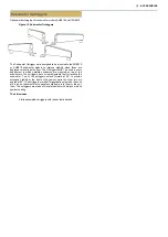
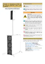
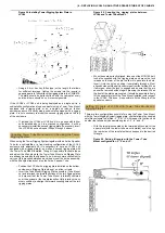
Figure 19. Threaded inserts for Tower Tube Mount
on the bottom of LCC44 or LCC84.
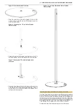
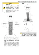
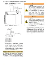
Figure 20. Removing screws from Tower Tube
Mount attachment points.
•
Invert the LCC44 enclosure and use a 4 mm Allen wrench or
hex driver to remove the two M6×16 mm screws from the rigging
points indicated above on the bottom side of the cabinet. Put
these aside, as they will be used to mount the Tower Tube
Mount.
•
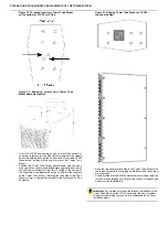
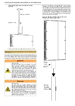
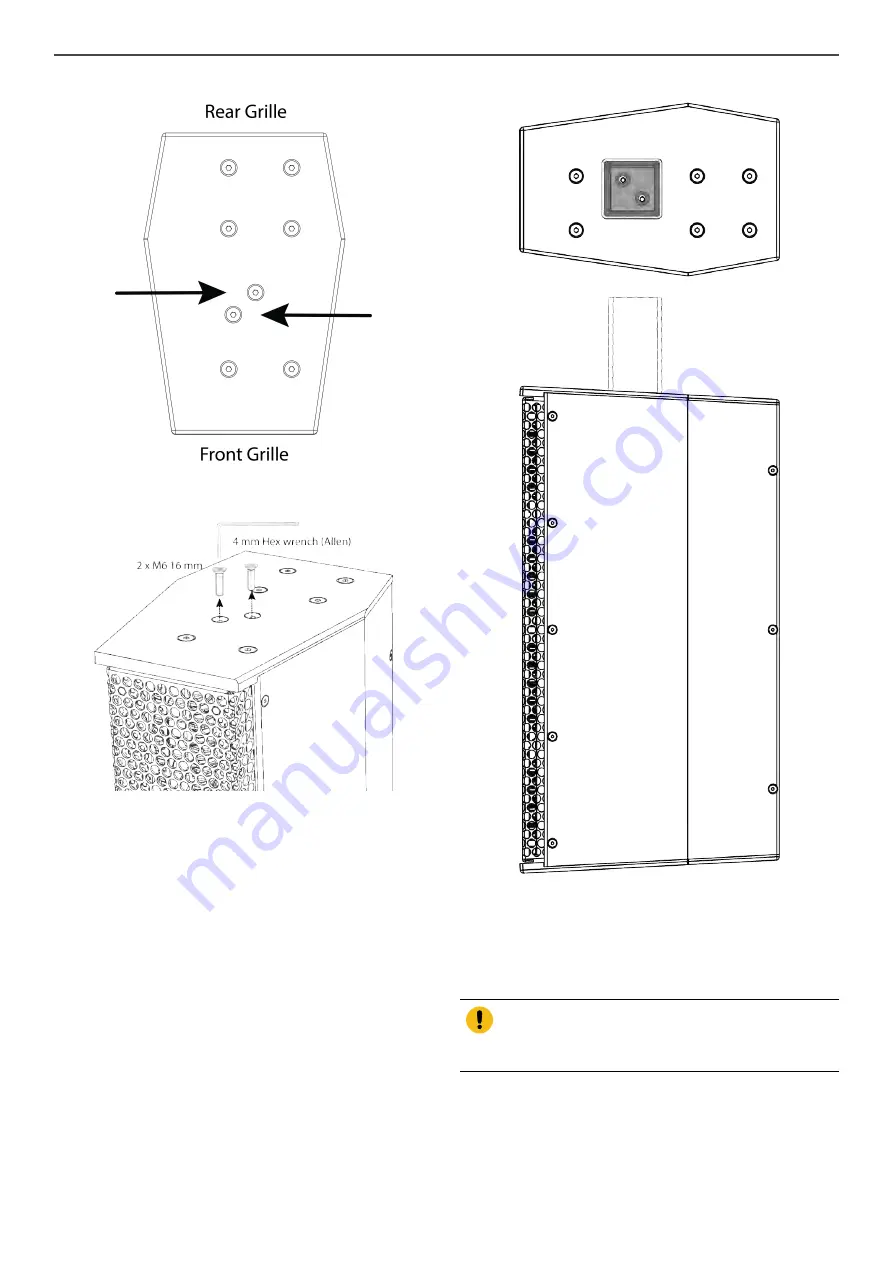
Position the Tower Tube Mount upside-down, with the open
side up and the countersunk-drilled plate against the bottom of
the enclosure, making sure that the -3° angle of the bottom of
the enclosure is complemented by the +3° angle of the top plate
of the Tower Tube Mount, returning the long side of the Tube
Mount to form a straight line parallel to the vertical axis of the
enclosure.
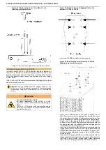
Figure 21. Aligning Tower Tube Mount on LCC44 –
top and side view.
•
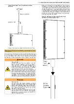
Align the two countersunk holes in the Tower Tube Mount with
the threaded inserts in the rigging points from which the screws
were removed.
•
Carefully thread the two M6x16 mm screws previously removed
into the inserts through the holes in the Mount. A magnetized
hex driver can facilitate this.
Important: For permanent or semi-permanent installation of the
Tower Tube Mount on the LCC44 enclosure, the use of medium-
strength threadlocking compound is recommended on all user-
installed screws.

