STACKED AND POLE-MOUNTED DEPLOYMENTS OF THE TOWER SYSTEM
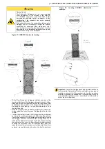
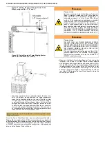
Figure 33. Aligning forward Outrigger on CSUB610
(side view)
•
Using a 5 mm hex wrench, fully tighten the countersunk M8
screw into the rigging point.
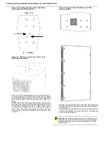
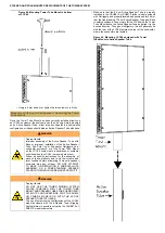
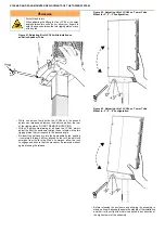
Figure 34. Aligning rear Outrigger on CSUB610
(bottom view)
•
Align the mounting hole of the shorter 90° Outrigger with the
bottom rigging point nearest the rear grille of the subwoofer and
thread in the M8 screw into the threaded insert of the rigging
point, making sure that the bottom bracket of the Outrigger fits
firmly around the rubber foot of the subwoofer and flush with the
bottom surface of the subwoofer cabinet.
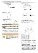
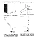
Figure 35. Aligning rear Outrigger on CSUB610
(side view).
•
Using a 5 mm hex wrench, fully tighten the countersunk M8
screw into the rigging point.
•
Repeat steps the steps above on the opposite side of the
CSUB610.
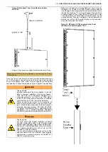
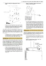
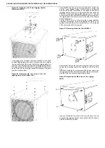
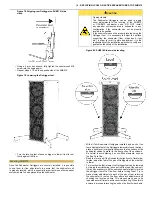
Figure 36. Lowering the Outrigger feet.
•
Turn the leveling feet of each outrigger to lower it just to rest
firmly against the floor.
Leveling CSUB610
Once the Subwoofer Outriggers are securely installed, it is possible
to use them for fine adjustments to assure that the subwoofer unit
is properly leveled, which is especially important when other speaker
enclosures are to be deployed atop the subwoofer.

