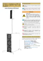
| 4 - DEPLOYING LCC44 ON AN ACTIVE SPEAKER TUBE ATOP CSUB610
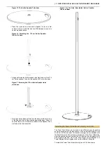
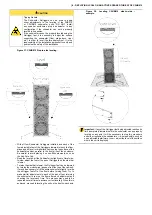
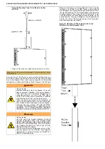
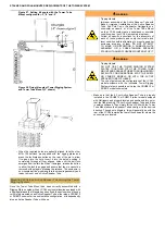
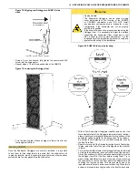
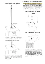
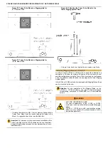
Figure 54. Installing Tower Rigging System Plate to
LCC44
•
Using a 4 mm hex key (Allen type) with a length that allows
for sufficient leverage, tighten the screws into the inserts in
opposing pairs to firmly attach the rigging plate to the CSUB610.
The plate should be perfectly flush with the cabinet at every
point and there should be no movement possible.
If the LCC44 or LCC84 unit is being deployed as a single unit in a
sub/satellite configuration atop a subwoofer using a Tower Tube Mount
equipped with a rigging plate, or as a single unit (with no further
enclosures above it) directly atop a subwoofer equipped with a rigging
plate, it is not necessary to mount the second rigging plate on the top
of the enclosure.
•
If, instead, the LCC44 or LCC84 unit is to be used with further
units installed above it in a stacked configuration, it will be
necessary to install the second rigging plate. If necessary, invert
the LCC44/84 unit and repeat Steps 2 though 6 above.
Coupling Tower Tube Mount and LCC44 using the Tower
Rigging System
When using the Tower Rigging System together with an Active Speaker
Tube for a sub/satellite or a free-standing configuration of the LCC44
enclosure with adjustable tilt, it is necessary to have an LCC44 unit
equipped with a rigging plate(s), as well as a second rigging plate with
the Tower Tube Mount installed. Though it is possible to couple these
and adjust the tilt angle while the Tower Tube Mount and Rigging Plate
are already mounted on the Speaker Tube, it is much more convenient to
carry out this process beforehand and then mount the entire assembly,
with the tilt angle already set, atop the Active Speaker Tube.
•
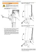
Position the LCC44 with a rigging plate installed on the bottom,
upside-down (Rigging Plate side up) on a floor or table.
•
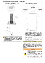
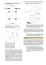
Invert the Tube Mount+Rigging Plate assembly (Tube Mount
up) and interlock the forward sections of the two rigging plates
in a manner that the Tower Tube Mount is laterally centered
over the enclosure (the two plates will not fully interlock in any
other condition), and align the forward coupling holes of the two
rigging plates.
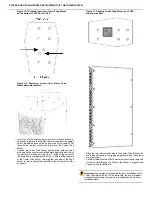
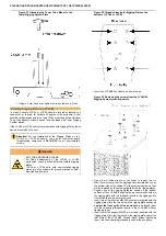
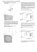
Figure 55. Coupling the rigging plates between
LCC44 and Tower Tube Mount.
•
When these are perfectly aligned, take one of the M10×100 ball-
lock pins supplied with the rigging plates and press the lock
release on the rear of the pin to allow it to pass into the hole.
Insert it into the holes, pushing it completely through all four
aligned holes until the ball-lock emerges from the far side. When
it emerges, allow the lock to engage and assure that the pin
cannot be removed without again pressing the release. When
the front of the plates are coupled, it should be possible to freely
tilt the upper plate (with the Tube Mount installed) with respect
to the LCC44. This done, it is possible to fix the tilt angle of the
speaker enclosure.
Setting tilt angle of LCC44 with Tower Tube Mount and
Rigging Plates
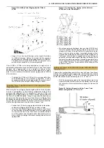
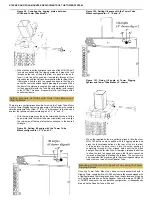
There are two configurations possible for using the Tower Tube Mount
with the Tower Rigging System rigging plate: one that allows the coupled
satellite enclosure to be tilted -3°, 0° or +3° with respect to the floor, and
another that allows only downward angles of -3°, -6° and -9°.
•
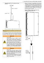
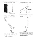
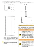
With the two plates coupled by the forward ball-lock pin, tilt the
upper plate (with the tower tube mount installed) so as to align
the rear holes of the two plates that correspond to the desired
tilt angle.
Figure 56. Setting tilt angle with the Tower Tube
Mount configured for -3°, 0° and +3°.

