STACKED AND POLE-MOUNTED DEPLOYMENTS OF THE TOWER SYSTEM
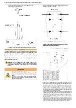
WARNING
Risk of Hand Injury
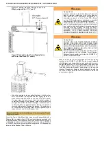
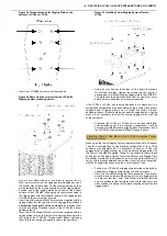
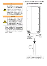
When adjusting the tilt angle of an LCC44 or the splay
angle between two units, do not allow your fingers to
enter the space between the two rigging plates or any
of the holes.
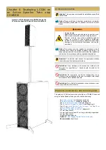
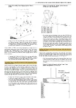
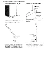
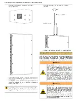
Figure 61. Adjusting tilt of LCC44 while installed on
an Active Speaker Tube.
•
While one person firmly holds the LCC44 unit, the second
person can release and remove the ball-lock pin from the rear
of the rigging plates. DO NOT REMOVE BOTH PINS.
•
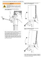
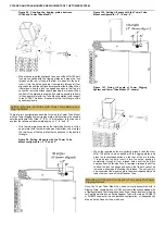
With one person maintaining at all times the LCC44, simply
adjust the tilt of the enclosure to align the set of holes in the two
rigging plates that correspond to the desired angle.
•
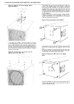
Re-insert the ball-lock pin into the appropriate holes, pushing
it completely through all four aligned holes until the ball-lock
emerges from the far side. When it emerges, allow the lock
to engage and assure that the pin cannot be removed without
again pressing the release.
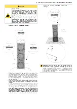
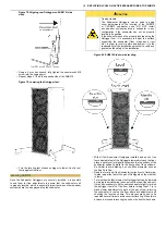
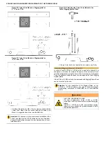
Figure 62. Adjusting tilt of LCC44 on Tower Tube
Mount in +3°,0°, -3° configuration.
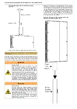
Figure 63. Adjusting tilt of LCC44 on Tower Tube
Mount in -3°,-6°, -9° configuration.
•
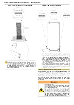
Before releasing the enclosure and allowing the assembly to
stand on its own, physically assure the stability of the installation
and that it will not tip with mild force applied in any direction at
the highest point of the assembly.


