| 5 - DEPLOYING LCC44 ON ACTIVE SPEAKER TUBE ATOP SUB310
•
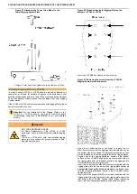
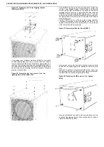
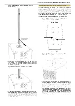
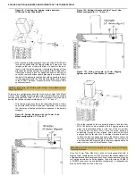
Make sure that the 95 cm Active Speaker Tube is properly
installed in the CSUB610 or SUB310 (either model equipped
with Outriggers and properly leveled and positioned for use) or
that the free-standing 175 cm Active Speaker Tube and Base
is safely positioned. Then simply lift the LCC44 with the Tower
Tube Mount above the Active Speaker Tube and align it in the
desired direction. Though not obligatory, this will generally be
with the rear of the LCC44 towards the rear of the subwoofer,
where the connectors are located.
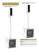
Figure 89. Mounting LCC44 equipped with Tower
Tube Mount to Active Speaker Tube.
•
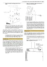
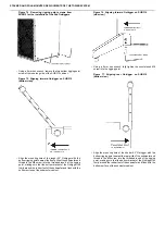
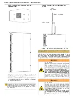
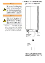
Lower the LCC44 enclosure and allow the Active Speaker Tube
to slide into the Tower Tube Mount, making sure that it does not
catch or bind as it enters. It should stop firmly when the Tube
arrives at the top of the Mount, with the bottom of the Tower
Tube Mount coming to 2 cm above the top SpeakOn connector.
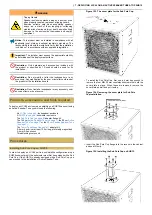
Figure 90. LCC44 with Tower Tube Mount installed
on Active Speaker Tube.
•
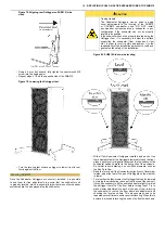
Physically assure the stability of the installation and that it will
not tip using mild force applied in any direction at the highest
point of the assembly.
Installing the Tower Tube Mount on a Tower Rigging
System Plate
When the application requires that the LCC44/84 unit be adjustable in
tilt with respect to the floor, the Tower Tube Mount can be attached to a
Tower Rigging System rigging plate to allow different tilt angles. There
are two configurations possible for using the Tower Tube Mount with the
Tower Rigging System rigging plate: one that allows the coupled satellite
enclosure to be tilted -3°, 0° or +3° with respect to the floor, and another
that allows only downward angles of -3°, -6° and -9°.
To attach the Tower Tube Mount to a Tower Rigging System rigging
plate:
•
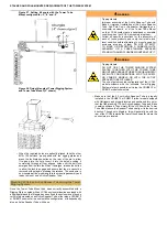
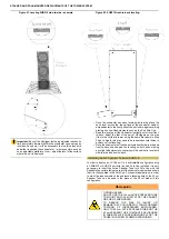
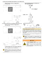
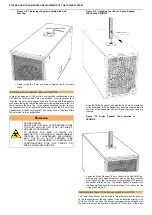
Lay the Tower Rigging System plate flat with the uniform
surface up.
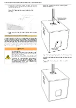
Figure 91. Mounting holes for Tower Tube Mount on
the Tower Rigging System plate.
•
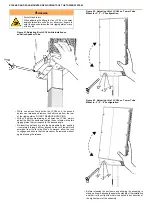
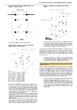
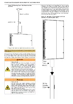
Position the Tower Tube Mount upside-down, with the open
side up and the countersunk-drilled plate against the bottom of
the rigging plate, in one of the two positions shown in the figures,
depending on the coverage required.
•
Align the two countersunk holes in the Tower Tube Mount with
the threaded holes in the plate shown in the figures, making
sure to achieve the desired tilt angle possibilities.


