STACKED AND POLE-MOUNTED DEPLOYMENTS OF THE TOWER SYSTEM
•
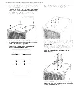
Insert and thread the four rubber feet removed above into the
corresponding rigging points on the opposite end of the cabinet.
Tighten these firmly by hand.
•
The cabinet can now be raised to the upright position, with the
mounting inserts for the Tower Rigging System plate on the top.
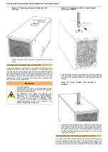
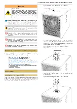
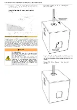
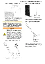
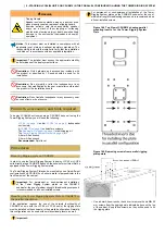
Figure 140. Replacing the M8 screws in the rigging
points left vacant by the rubber feet.
•
Insert and thread the four countersunk M8×25 mm screws into
the rigging points from which the four rubber feet were removed.
Use the 5 mm hex wrench to tighten these.
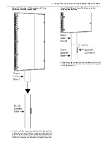
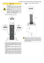
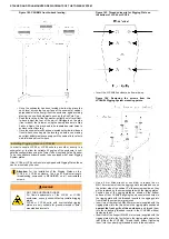
Figure 141. The threaded inserts for mounting the
Tower Rigging System plate on SUB310.
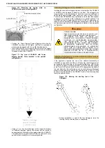
Figure 142. Removing the screws from the inserts
for mounting the Tower Rigging System plate.
•
Use a 4 mm Allen wrench or hex driver to remove the six M6×50
mm screws from the rigging points indicated above on the top
of the cabinet. Keep these screws, as they will be used to fix
the rigging plate.
•
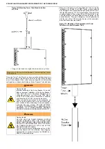
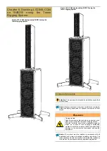
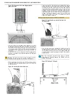
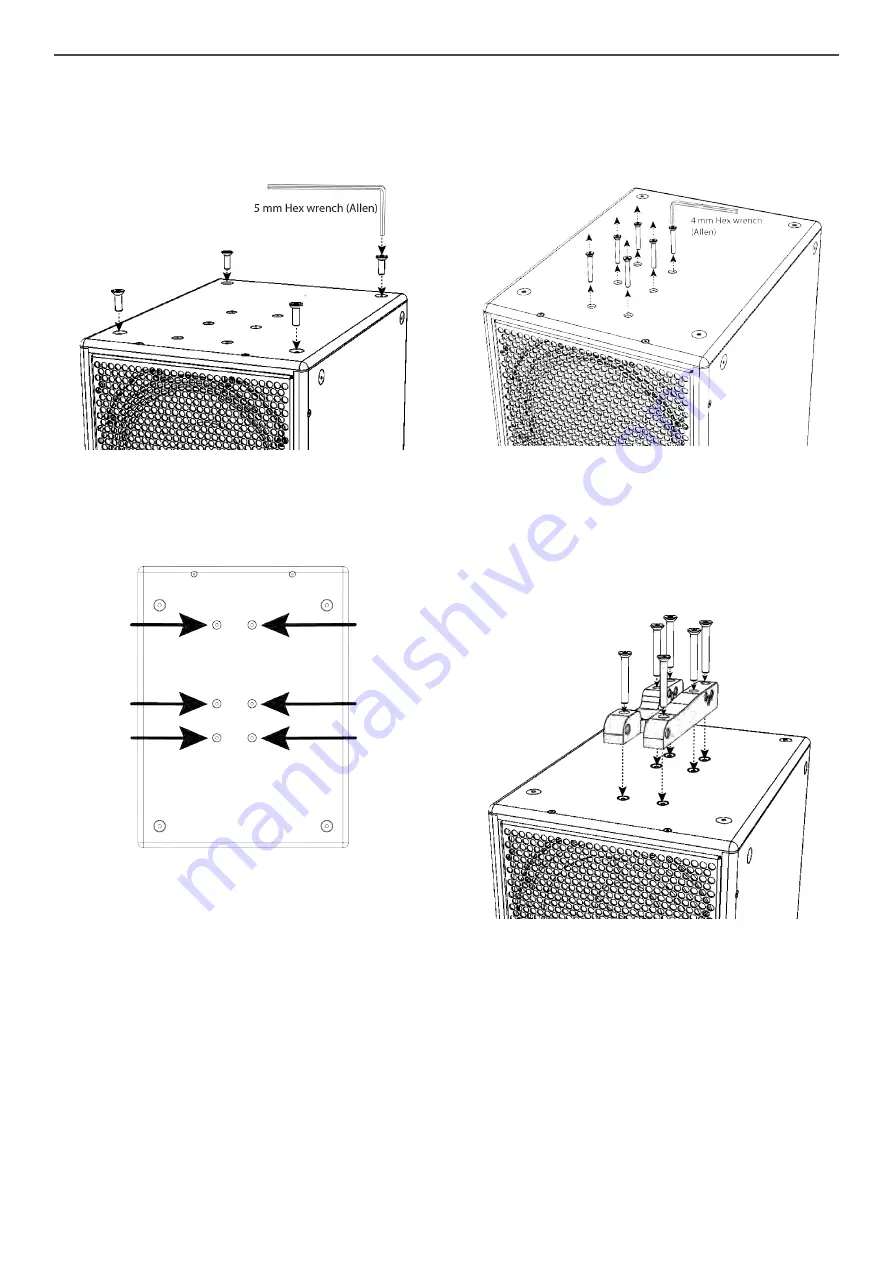
Position the Tower Rigging System Rigging plate atop the
SUB310, as shown in the figure, with the six countersunk
mounting holes aligned with the six M6 threaded inserts.
Figure 143. Installing the Tower Rigging System
plate on SUB310.
•
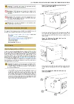
Insert the six M6×50 mm screws into the six holes in the rigging
plate. Thread these without tightening them into the underlying
threaded inserts in the SUB310.


