| 9 - STACKING LCC44/84 UNITS ON CSUB610 IN THE PARALLEL CONFIGURATION USING THE TOWER RIGGING SYSTEM
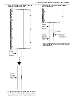
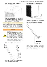
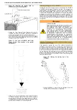
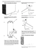
Figure 173. Removing rigging point screws from
CSUB610 for the installation of the Sub Outriggers
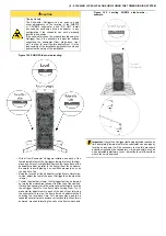
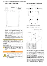
Figure 174. Configuring the outriggers on CSUB610
for parallel deployment of LCC44/84 units (bottom
view).
•
Using a 5 mm hex wrench, remove the two bottom rigging point
screws from one long side of the CSUB610 cabinet.
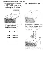
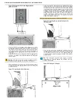
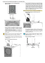
Figure 175. Aligning forward Outrigger on CSUB610
(bottom view).
•
Align the mounting hole of the longer 50° Outrigger with the
bottom rigging point nearest the front grille of the subwoofer and
thread in the M8 screw into the threaded insert of the rigging
point, making sure that the bottom bracket of the Outrigger fits
firmly around the rubber foot of the subwoofer and flush with the
bottom surface of the subwoofer cabinet.
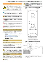
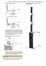
Figure 176. Aligning forward Outrigger on CSUB610
(side view)
•
Using a 5 mm hex wrench, fully tighten the countersunk M8
screw into the rigging point.

