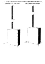
| 9 - STACKING LCC44/84 UNITS ON CSUB610 IN THE PARALLEL CONFIGURATION USING THE TOWER RIGGING SYSTEM
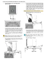
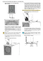
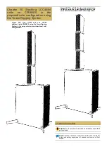
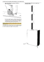
Figure 197. Alignment of the Tower Rigging System
plates, front view.
•
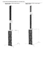
Lift the LCC84 or LCC44 above the rigging plate of the first
coupled LCC44/84. The two rigging plates should align to
interlock, as in the figure.
•
Lower the LCC84 onto the subwoofer so that the rigging plates
interlock. The shape of the plates themselves will help align
them correctly.
Attention: Until both lock pins have been completely inserted
and locked, maintain a grip on the upper LCC44 (or LCC84) unit.
•
While maintaining a firm hold on the upper enclosure, slide it to
align the holes in the rigging plates closest to the front grille of
both enclosures.
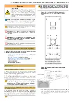
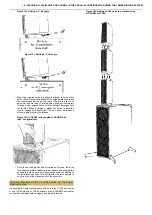
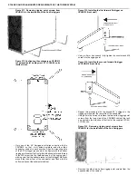
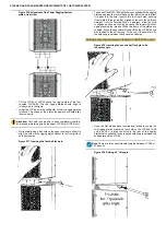
Figure 198. Inserting the first ball-lock pin.
•
Take one of the M10×100 ball-lock pins supplied with the rigging
plates and press the lock release on the rear of the pin to allow
it to pass into the hole. Insert it into the front holes, pushing
it completely through all four aligned holes until the ball-lock
emerges from the far side. When it emerges, allow the lock
to engage and assure that the pin cannot be removed without
again pressing the release. When the fronts of the plates are
coupled, it should be possible to freely tilt the top LCC84/44 unit
with respect to the bottom one. This done, it is possible to fix
the splay angle between the speaker enclosures.
Setting splay angle between stacked LCC44/LCC84 units
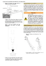
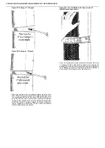
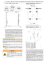
Figure 199. Inserting the second ball-lock pin to fix
the splay angle.
•
Once the first pin has been inserted and locked to couple the
two rigging plates, maintain a firm hold on the LCC84/LCC44
unit, and tilt it to align the holes in the rear of the rigging
plates that correspond to the required splay angle between the
subwoofer and the LCC84.
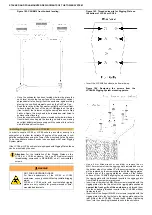
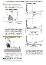
Note: There are three possible splay angles between LCC84 or
LCC44 units.
Figure 200. Setting a 0° tilt angle.


