| 10 - STACKING LCC44/84 UNITS ON CSUB610 IN THE PERPENDICULAR CONFIGURATION USING THE TOWER RIGGING SYSTEM
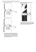
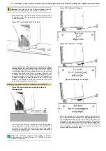
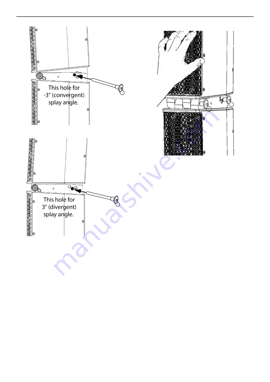
Figure 240. Setting a -3° tilt angle.
Figure 241. Setting a 3° tilt angle.
•
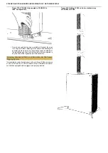
When the required holes are perfectly aligned, take the other
M10×100 ball-lock pin supplied with the rigging plates and press
the lock-release button on the rear of the pin to allow it to
pass into the hole. Insert it into the holes, pushing it completely
through all four aligned holes until the ball-lock emerges from
the far side. When it emerges, release the button to allow the
lock to engage and assure that the pin cannot be removed
without again pressing the release.
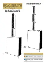
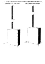
Figure 242. Two LCC84/44 units fully coupled, 0°
(parallel) splay angle shown.
•
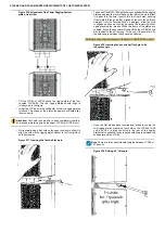
Once the second pin has been inserted and locked, the array
is configured. Before releasing the enclosure and allowing the
assembly to stand on its own, physically assure the stability of
the installation and that it will not tip with mild force applied in
any direction at the highest point of the assembly.
•


