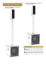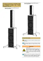
| 7 - DEPLOYING LCC44 ON AN ACTIVE SPEAKER TUBE ATOP SUB12
WARNING
Tipping Hazard
Speaker enclosures stacked atop one another, even
when properly coupled, represent a tipping hazard.
Exercise extreme care when assembling speaker
arrays, as a stack of them toppling or collapsing
creates a risk of serious injury or death, as well as likely
damage to the enclosures themselves and nearby
equipment.
Notice: This product must be installed in compliance with all
applicable local, state and national regulatory provisions. The
responsibility rests with the installer to verify that the installation
is carried out in accordance with any applicable legislation.
Important: The installer must assess the appropriate stability
and sturdiness of the deployment surface.
Restriction: Only hardware and accessories included with
the product or specified by 1 Sound should be used for its
installation.
Restriction: Do not modify or alter the loudspeaker or any
accessory. Any modification by the user or installer could render
the product or the installation unsafe.
Restriction: Do not install a loudspeaker or any accessory near
any open flame or heat source.
Products, accessories and tools required
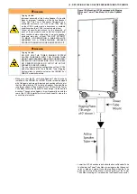
To deploy an LCC44 enclosure as a satellite on a SUB12 bass unit using
an Active Speaker Tube you will need the following:
•
loudspeaker enclosure
•
subwoofer enclosure
•
•
The 145 cm
Active Speaker Tube (on page 7)
, the 95 cm
or the
•
adapter kit
•
A 4 mm hex driver at least 10 cm long, preferably magnetized
•
A 4 mm Allen wrench
•
Threadlocking compound
Procedures
Installing Sub Pole Cup on SUB12
In order to deploy an LCC44 unit in a sub/satellite configuration atop a
SUB12 subwoofer unit, the subwoofer must first be equipped with a Sub
Pole Cup. If the SUB12 is already equipped with a Sub Pole Cup, you
can proceed to the installation of Active Speaker Tube.
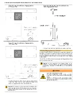
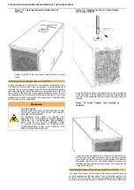
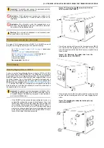
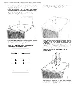
Figure 123. The cover plate for the Sub Pole Cup.
•
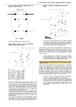
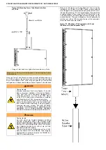
To install the Sub Pole Cup, first use a 4 mm hex wrench to
remove the four M6×20 mm countersunk screws that hold the
cover plate in place. When these are removed, remove the
cover plate as well and put it aside.
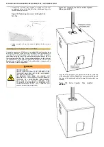
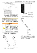
Figure 124. Removing the cover plate for Sub Pole
Cup installation.
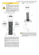
•
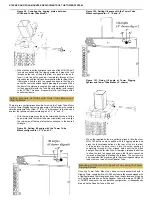
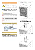
Insert the Sub Pole Cup flange into the recess in the cabinet
and seat it firmly.
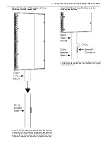
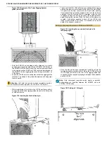
Figure 125. Installing the Sub Pole Cup on SUB12.


