STACKED AND POLE-MOUNTED DEPLOYMENTS OF THE TOWER SYSTEM
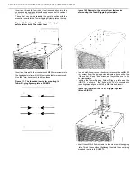
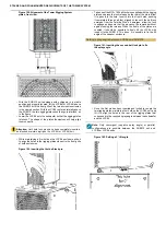
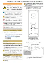
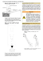
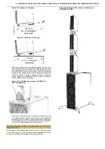
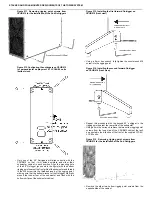
Figure 182. CSUB610 front-to-back leveling.
•
Once the subwoofer has been leveled side-to-side, place the
spirit level across the top surface of the subwoofer cabinet,
perpendicular to the front grille of the enclosure, again avoiding
placing it on non-flush elements, such as the Sub Pole Cup.
•
Read the level, and if the Subwoofer is slightly out of level front-
to-back, adjust the feet of the pair of Outriggers on the side
(front or back) that is lower, using the same procedure in Step
3 above. Again, this may need to be repeated several times to
achieve correct leveling.
•
Once the subwoofer unit has been leveled both side-to-side and
front-to-back, check again the leveling on both axes, making
any slight adjustments necessary until the cabinet is level both
side-to-side and front-to-back.
Installing Rigging Plate on LCC44/84
In order to couple LCC44 or LCC84 units to each other, directly to a
subwoofer, or to allow for variable tilt angles of the enclosure in sub/
satellite configurations using the Tower Tube mount and Active Speaker
Tube, the speaker enclosure needs to be equipped with Tower Rigging
System plates.
If the LCC44 or LCC84 unit is not pre-equipped with Rigging Plates, these
can be mounted by the user.
Attention: For the installation of the Rigging Plates on the
LCC44 or LCC84 enclosure, the use of medium-strength
threadlocking compound is REQUIRED on all user-installed
screws.
WARNING
NOT FOR SUSPENDED LOADS
For flown deployments of the LCC44 or LCC84
enclosures, use only units with factory-installed rigging
plates.
LCC44 or LCC84 units with user-installed rigging
plates are only suitable for ground-stacked or pole-
mounted deployments.
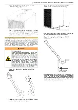
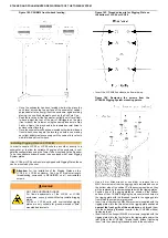
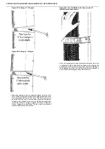
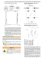
Figure 183. Threaded inserts for Rigging Plate on
the bottom of LCC44 or LCC84.
•
Invert the LCC44/84 enclosure, bottom-side-up.
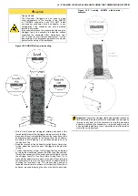
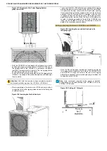
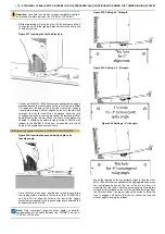
Figure 184. Removing the screws from the
LCC44/84 Rigging System mounting points.
•
Use a 4 mm Allen wrench or hex driver to remove the six
M6×16 mm screws from the rigging points indicated above on
the bottom side of the cabinet. Put these screws aside, as they
will be replaced by the screws supplied with the rigging plates.
•
Position one of the rigging plates as shown on the bottom
surface of the LCC44/84, aligning the six countersunk holes in
the rigging plate with the threaded inserts in the rigging points
from which the screws were removed.
•
Insert two of the (shorter) M6×45 mm screws (supplied with the
rigging plates) into the two holes in the rigging plate positioned
nearest the front grille of the enclosure, and thread them
into the underlying threaded inserts in the LCC44/84 without
tightening them.
•
Insert four of the (longer) M6×50 mm screws (supplied with the
rigging plates) into the four holes in the rigging plate nearer the
rear grille of the LCC44/84. Thread these, without tightening
them, into the underlying threaded inserts in the enclosure.

