STACKED AND POLE-MOUNTED DEPLOYMENTS OF THE TOWER SYSTEM
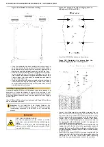
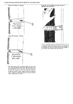
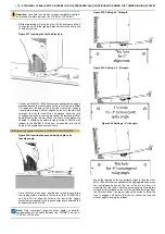
Figure 224. Installing Tower Rigging System Plate
to LCC44
•
Using a 4 mm hex key (Allen type) with a length that allows
for sufficient leverage, tighten the screws into the inserts in
opposing pairs to firmly attach the rigging plate to the CSUB610.
The plate should be perfectly flush with the cabinet at every
point and there should be no movement possible.
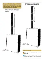
If the LCC44 or LCC84 unit is being deployed as a single unit in a
sub/satellite configuration atop a subwoofer using a Tower Tube Mount
equipped with a rigging plate, or as a single unit (with no further
enclosures above it) directly atop a subwoofer equipped with a rigging
plate, it is not necessary to mount the second rigging plate on the top
of the enclosure.
•
If, instead, the LCC44 or LCC84 unit is to be used with further
units installed above it in a stacked configuration, it will be
necessary to install the second rigging plate. If necessary, invert
the LCC44/84 unit and repeat Steps 2 though 6 above.
Coupling LCC44/84 units to CSUB610 using Tower Rigging
System
Once a CSUB610 has been equipped with outriggers, leveled, and
a Tower Rigging System plate has been properly installed, it can be
coupled in stacked configuration with LCC84 or LCC44 units likewise
equipped with rigging plates.
WARNING
Tipping Hazard
Improper installation of the Subwoofer Outriggers or
the Tower Rigging System plate on a subwoofer
enclosure, or of the rigging plate on the LCC44 or
LCC84 unit could create a hazardous or unstable
condition when the subwoofer and column enclosure
are assembled.
Follow all specific instructions for the assembly
of each of these products and verify their stable
and level condition before attempting to mount
a speaker enclosure atop any of them. DO
NOT ATTEMPT TO MOVE OR REPOSITION A
SUB/SATELLLITE ASSEMBLY OR STACKED AND
COUPLED SPEAKER ARRAY.
WARNING
Tipping Hazard
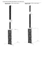
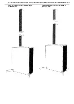
The CSUB610 model subwoofer is designed for use in
a stacked and coupled configuration with a maximum
of one (1) LCC84 unit plus one (1) LCC44 unit, or three
(3) LCC44 units. Mounting further enclosures atop the
CSUB610 can render the entire assembly unstable.
WARNING
Risk of Hand Injury
When coupling or setting the splay angle between two
LCC44/84 units or a subwoofer unit and an LCC44/84
unit, do not allow your fingers to enter the space
between the two rigging plates or any of the holes.
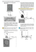
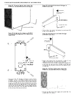
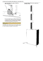
Figure 225. Placing LCC84 atop CSUB610 for
coupling in the perpendicular configuration.
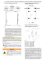
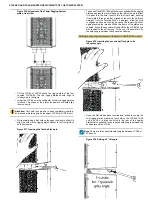
Figure 226. Alignment of the Tower Rigging System
plates, front view.
•
With the CSUB610 unit equipped with outriggers in a stable
position and properly leveled, lift the LCC84 or LCC44 above
the rigging plate of the CSUB610, in whichever orientation
(parallel or perpendicular) is required. The two rigging plates
should align to interlock, as in the figure.
•
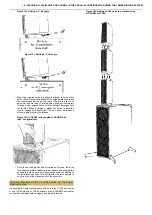
Lower the LCC84 onto the subwoofer so that the rigging plates
interlock. The shape of the plates themselves will help align
them correctly.

