background image

TOWER SYSTEM LCC44/LCC84 WALL INSTALLATION

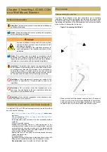
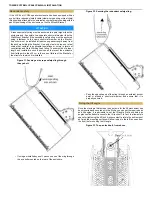
Mounting the bracket

The mounting plate of the LCC44/84 Wall Bracket must be firmly fitted to 
the wall or surface before mounting and pointing the speaker enclosure.

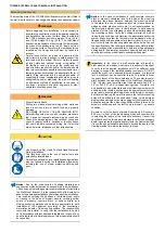
 WARNING

Before  beginning  this  installation,  it  is  necessary  to 
ascertain the construction type, load-bearing capability 
and durability of the wall or surface. Bear in mind that 
the  LCC44  speaker  enclosure  weighs  10  kg  (22  lb) 
and  LCC84  weighs  19.5  kg  (43  lb).  The  Wall  Mount 
Bracket is also capable of downward tilt that extends 
the mass of the enclosure up to a 40° angle out from 
the mounting surface. Therefore, the increased forces 
imposed  on  the  fixings  and  wall  must  be  taken  into 
account.
Careful  thought  must  be  given  to  ensure  that  the 
wall  structure  is  strong  enough  to  safely  support  the 
total  load  with  the  proper  Factor  of  Safety  required 
by  local,  state  and  national  norms  or  legislation.  If 
the  facility  or  venue  is  open  to  the  public  and  the 
mount is within reach of the public, the installer should 
take into consideration possible miscreant behavior or 
tampering when determining the appropriate factor of 
safety.  If  the  wall  structure  is  deemed  incapable  of 
supporting the load, consideration should be given to 
strengthening  and/or  stabilizing  the  wall  or  adopting 
an  alternative  method  of  installation.  In  the  case  of 
any  doubt,  architects,  structural  engineers  or  other 
specialists should be consulted.

 WARNING

Risk of Electric Shock
Drilling  into  hidden  electrical  wiring  within  walls  can 
result  in  serious  injury  or  death,  fires  and  property 
damage.
BE  AWARE  OF  WHAT  YOU  ARE  DRILLING  INTO. 
Before drilling holes in any wall or surface, make sure 
that  it  does  not  conceal  electrical  wiring  or  conduits. 
Consult the wiring diagram of the facility or venue and 
check  for  nearby  outlets,  switches  or  junction  boxes 
that  could  indicate  concealed  wiring,  be  it  electrical 
mains, network, telephone or other infrastructure.

 CAUTION

Use Proper Eye, Ear, Head, Foot and Hand Protection 
During Installation
This  task  may  require  the  use  of  power  tools  and 
potentially elevated loads.
All local and national norms, regulations and guidelines 
must  be  followed  during  the  installation  procedures, 
including  the  use  of  proper  protective  clothing  and 
gear.

Notice:   Due  to  the  wide  variety  of  building  materials  and 
construction methods that can be encountered in an installation, 
1 Sound can only provide general recommendations for installing 
the Wall Mount Bracket. It is the responsibility of the installer to 
assess the appropriate stability and sturdiness of the installation. 
This  includes  verifying  the  positions  of  suitable  studs,  posts 
or  framing  in  the  case  of  drywall  mounts,  verifying  hollow 
points  in  masonry,  concrete  block  or  solid  concrete,  and 
utilizing anchoring methods and hardware appropriate for safe 
installation  of  the  equipment  according  to  the  construction 
material  and  depth  of  the  mounting  surface.  The  responsibility 
rests  with  the  installer  to  verify  that  the  installation  is  carried 
out in accordance with any applicable legislation. In case of any 
doubt, architects, structural engineers or other specialists should 
be consulted.

Notice:   In  the  case  of  installation  in  solid  concrete,  concrete 
block  or  masonry  structures,  due  to  the  size  of  the  mounting 
plate  and  the  narrow  distance  between  the  mounting  holes 
in  the  plate,  the  use  of  expansion  anchors  (sleeve  anchors, 
wedge  anchors,  plastic  anchors  etc.)  is  not  recommended,  as 
the  proximity  between  them  is  likely  inferior  to  safe  spacing 
practices for this type of fastener, and could potentially weaken 
the  mounting  surface.  Verify  the  building  material,  as  well  as 
its depth and condition to determine the appropriate anchoring 
system. Make sure that the fasteners include washers or have 
flanged heads with adequate outer diameter (from 14 mm to 16 
mm) to firmly hold the mounting plate around the holes. Consult
the specifications of the third-party hardware and carefully follow
the instructions of the manufacturer to determine the appropriate
drilling  depth,  bit  diameter,  necessary  spacing  and  any  further
specific instructions or additional necessary procedures.

Important:   In  the  case  of  a  wall  constructed  of  drywall  or 
other panels on a wooden stud frame, it is extremely important 
to  verify  that  the  desired  installation  point  has  sufficient  solid 
backing  to  support  the  installed  speaker  enclosure.  DO  NOT 
install  the  mount  on  unbacked  drywall,  plywood  or  plastered 
lath. A studfinder can be useful for this, but it is better to know 
the exact layout of the frame beforehand. The center-to-center 
width between the mounting holes of the Wall Mount Bracket is 
1.89"  (48  mm),  and  therefore  wider  than  standard  2x4  (1.5"  x 
3.5") or 2x6 (1.5" x 3.5") wooden framing studs. Therefore, it is 
only possible to mount the plate onto other framing members with 
doubled or wider widths, such as doubled posts or column studs, 
corner posts, doubled jamb/king studs, solid lintels, or purpose-
built internal framing. Be careful to assure that all four mounting 
holes  will  be  drilled  into  the  solid  wood  frame.  Joints  between 
single studs and single horizontal noggings or fireblocks could be 
deceptive and provide a mounting position with only three of the 
screws in solid wood and the fourth only in drywall – an unsafe 
condition.

Be sure to verify the depth of drywall (commonly 0.5 inches or 
6.35  mm)  in  front  of  the  load-bearing  studs  and  consider  this 
in  selecting  the  length  of  the  fastener  necessary.  Consult  the 
specifications of the third-party hardware to verify the necessary 
depth to guarantee the required safety factor, but remember that 
it is unwise and potentially hazardous to exceed the depth of the 
framing member into which the anchor is driven.

Summary of Contents for LCC44

Page 1: ...W O R K I N G D R A F T 1 SOUND INC 34 Apple Street Tinton Falls NJ 07724 1 732 798 9900 www 1 sound com Tower Series LCC44 LCC84 Wall Installation ...

Page 2: ...stalling LCC44 LCC84 on a Wall Mount Bracket 5 Critical information 5 Products accessories and tools required 5 Procedures 5 Disassembling the bracket 5 Installing the bracket on the LCC44 LCC84 enclosure 7 Installing a redundant safety anchor 9 Mounting the bracket 10 Coupling the LCC enclosure and bracket to the mounting plate 12 Redundant safety 14 Fixing the tilt angle 14 Fixing the pan angle ...

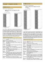
Page 3: ...ious lengths Dimensions 17 8 452 mm x 6 3 160 mm x 9 5 240 mm Colors Stocking black and white custom colors and fabrics available TOWER LCC84 Cardioid Column Line Array Enclosure Figure 2 LCC84 with Tower Rigging System left and without Tower LCC84 is a cardioid line array element featuring designed to be compact high powered and array able The enclosure features Clarity Technology a proprietary h...

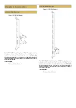
Page 4: ...le person and is available with a black or white finish as standard The kit includes The assembled wall bracket LCC84 Wall Bracket Figure 4 LCC84 Wall Bracket The LCC84 Wall Bracket attaches to an LCC84 Tower loudspeaker in order to mount to a wall or ceiling To provide versatility in terms of installation and to adapt to the coverage requirements of the speaker enclosure the bracket is articulate...

Page 5: ...nsafe Restriction Do not install a loudspeaker or any accessory near any open flame or heat source Products accessories and tools required To install an LCC44 or LCC84 enclosure permanently on a wall or surface you will need the following An LCC44 on page 3 or LCC84 on page 3 loudspeaker enclosure The corresponding LCC44 on page 4 or LCC84 Wall Mount Bracket on page 4 kit An appropriate power dril...

Page 6: ...nism and remove this clevis pin Put the pin and the R clip aside as they will be required to complete the installation Figure 7 Removing the clevis pin from the tilt mechanism Tilt the bracket outwards from the mounting plate until it comes to a stop at its maximum tilt Figure 8 Removing the bracket from the mounting plate The bracket should come away easily towards the bottom of the mount ...

Page 7: ...stallation of the bracket LCC44 shown Lay the enclosure on its front grille taking whatever necessary precautions to avoid damaging the finish of the cabinet or the grille Although the LCC44 and LCC84 units have a symmetrical vertical coverage and there is no top or bottom acoustically if the front grille is equipped with a logo plate you should note its orientation and for aesthetic reasons and m...

Page 8: ...rews previously removed and thread it into the bottom toward floor panel of the enclosure through the mounting hole in the bracket Figure 13 Inserting the upper screw through the bracket The upper end of the bracket can be secured using the second M8 x 20 mm screw previously removed Insert the screw and thread it into the top toward ceiling panel of the enclosure through the upper mounting hole in...

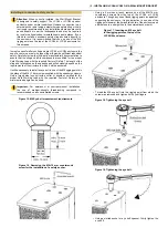
Page 9: ...ents of the structure to which it will be anchored It will be necessary to install an eye bolt in one of the M6 rigging points in the place of the M6 16 mm screw supplied with the speaker enclosure Only a forged steel eye bolt with a collar or shoulder certified for the proper Safe Working Load with the required Factor of Safety at its minimum load angle can be used Important For permanent or semi...

Page 10: ... utilizing anchoring methods and hardware appropriate for safe installation of the equipment according to the construction material and depth of the mounting surface The responsibility rests with the installer to verify that the installation is carried out in accordance with any applicable legislation In case of any doubt architects structural engineers or other specialists should be consulted Not...

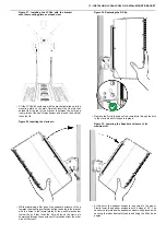
Page 11: ... Drill the four holes using a drill or percussion drill with a bit approriate to the substrate material masonry concrete wood steel etc with the appropriate diameter and to the appropriate depth for the anchor type being used Once the four mounting holes have been drilled clear them of residue and verify the appropriate depth of each Place the mounting plate against the wall in the correct orienta...

Page 12: ...igure 24 Tightening the screw anchors with a torque wrench Using a torque wrench tighten each screw anchor into the wall Take care not to exceed the maximum installation torque specified by the manufacturer of the hardware Figure 25 Applying downward force to verify the mount Apply force or weight to the mounting plate to physically verify its ability to support the necessary load There must be no...

Page 13: ... the mounting surface and align the holes in the bracket with the holes in the lateral plates of the pan tilt mechanism below the bolt that locks the tilt and insert the clevis pin completely through these holes until it protrudes from the other side of the mount Figure 29 Replacing the R Clip Replace the R clip hairpin cotter completely through the hole in the clevis pin until it snaps into place...

Page 14: ...gth and installed in such a position as to prevent the enclosure from falling more than 20 cm in the case of failure of the Bracket or the structure to which it is installed Figure 31 Passing a wire rope safety sling through the eye bolt If using an installed eye bolt pass one end of the sling through the eye bolt mounted on the rear of the enclosure Figure 32 Securing the redundant safety sling P...

Page 15: ...angle is as simple as turning the LCC44 or LCC84 enclosure to the desired angle and locking it in place by tightening the pan lock bolt Note The panning range of the Wall Mount Bracket is 90 from the center However this range may be limited on one or both sides by the mounting surface due to the width of the rear panel of the LCC44 or LCC84 enclosure If the Bracket is installed on a flat wall the ...

Page 16: ...Jersey 07724 U S A tel 1 732 798 9900 www 1 sound com sales 1 sound com 2022 1 SOUND All rights reserved No part of this publication may be reproduced or transmitted in any form or by any means without the express written consent of the publisher ...

Reviews: