Page 12
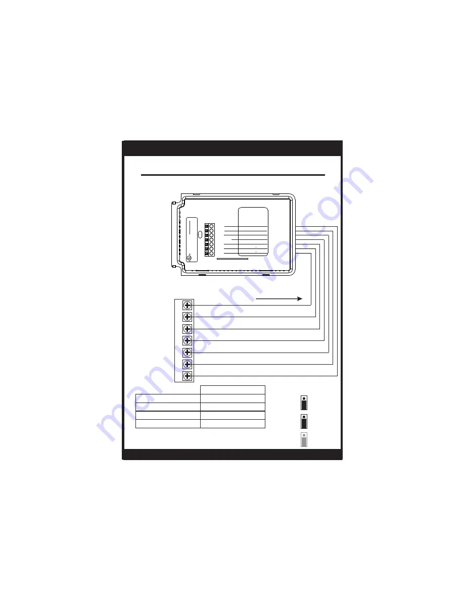
Sample Wiring Diagrams
7 Conductor 18 to 22 gauge
unshielded cable from the
thermostat to the equipment.
FAN
G
POWER
R
W2
AUXILIARY HEAT
COMPRESSOR
Y
INSTALLATION INSTRUCTIONS
MODEL
:
S1-TBEU22P7S
MADE IN CHINA
LIS
TED
4Z95
24V
. 60HZ
NEC CLASS 2
C
R
Y1
W1/O/b
G
W2
Y2
ENCLOSED
ENERGY
MAN
AGEMENT
EQUIPMENT
COMMON
C
2ND STAGE COOL
Y2
7 Wire, Two Stage Gas Furnace and Two Stage Cooling
Residential Gas Heat, Electric Cool, split systems & package units.
W
GAS HEAT
GAS
GAS
JP 1
JP 2
JP 3
ELEC
HP
O
B
JUMPER SETTINGS
*In this application 24v will not be present at
the ‘G’ terminal. The fan will be controlled by
the Gas Furnace.
With Demand
ACTIVE OUTPUTS
1st Stage Cooling
1st Stage Heating
2nd Stage Heating
2nd Stage Cooling
Y, G
W1, (G)*
Y2,
Y, G
W2,
W1, (G)*
S1-TBEU22P7S


