background image

NO. 

NAME 

QTY. 

NO. 

NAME 

QTY. 

Main frame 

42 

magnet plate 

Rear stabilizer 

43 

flat washer 

15 

Front stabilizer 

44 

revolving shaft 

Seat sliding set 

45 

circlip 

SeatMain fra 

46 

screw 

Pulley 

47 

Flywheel axle 

Sliding rail 

48 

Bearing 

Handle bar 

49 

Screw 

Console 

50 

Nut 

10 

Knob 

51 

Guide pulley sleeve 

11 

Pedal 

52 

Belt guide pulley 

12 

tube plug left-front stabilizer 

53 

M10*1.5 Bolt 

13 

Adjusting tube plug-rear stabilizer 

54 

M10*1.5 Pedal pole 

14 

Console wire 

55 

Washer 

15 

screw 

56 

Adjusting foot pad 

16 

sensor fixed base 

57 

M8*1.25 bolt 

17 

adapter 

58 

Hexagonal head bolt M8×35L 

18 

Sensor wire 

59 

Bearing 

19 

Pedal support tube 

60 

M8 nylon nut 

20 

Tube plug 

61 

Rivnut 

21 

Curved washer 

62 

Roller 

22 

bolt 

63 

Tube plug 


23 


flywheel 


64 

Roller limit sleeve

40×φ8x9.5 

POM 


24 

cover-left 

65 

plug 

25 

cover-right 

66 

M10X1.5bolt 

26 

handle bar foam 

67 

Bolt 

27 

spring case 

68 

Screw 

28 

crash pad 

69 

Spring washer 

29 

console support tube 

70 

Screw 

30 

tube plug right-front stabilizer 

71 

Flat washer 

31 

handle bar socket 

72 

Bolt 

32 

M10 nylon nut/lock nut 

73 

Nut 

33 

belt 

74 

Pressure spring 

34 

spring 

75 

Screw 

35 

pinch roller fixing plate 

76 

Screw 

36 

spacer bush 

77 

screw 

37 

Pinch roller bolt 

78 

Motor 

38 

Pinch roller 

79 

speed sensor wire 

39 

spacer sleeve 

80 

power connect wire 

40 

flat gasket 

10 

81 

Motor wire 

41 

bolt 

82 

Pulley casing 

Summary of Contents for 160B-motor

Page 1: ...OWNER S MANUAL 160B motor CONTENTS IMPORTANT SAFETY INFORMATION EXPLODED VIEW ASSMEBLY DRAWING ASSEMBLY INSTRUCTIONS COMPLETE EXPLOSION DRAWING WWW HUNDREDFIT COM ...

Page 2: ...onditions that could create a risk to your health and safety or prevent you from using the equipment properly Your doctor s advice is essential if you are taking medication that affects your heart rate blood pressure or cholesterol level 5 Be aware of your body s signals Incorrect or excessive exercise can damage your health Stop exercising if you experienced any of the following symptoms pain tig...

Page 3: ...eekly maintenance Check them before use every time If anything broken or loose please fix them immediately You may continue using them only after they return to good conditions 17 Pay attention to the absence of a free wheel system which will cause serious risk 18 Keep power cord away from heat sources 19 Do not insert or drop any object into any opening 20 Unplug exercise bike before moving or cl...

Page 4: ...EXPLODED VIEW ASSMEBLY DRAWING ...

Page 5: ...ASSEMBLY INSTRUCTIONS ...

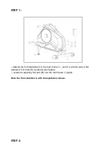
Page 6: ...ilizer 3 to the main frame 1 and fix it with two sets of flat washers 71 bolts 72 by allen wrench tightly screw the adjusting foot pad 56 into the main frame 1 tightly Note the front stabilizer is with transportation wheels STEP 2 ...

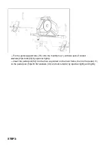
Page 7: ... 1 with two sets of curved washers 21 bolts 22 by spanner tightly insert the pedal pole 54 into the hole as pointed on the main frame then fix the pedal 11 on the pedal pole 54 with flat washers 40 and lock nuts 32 by spanner tightly and rightly STEP3 ...

Page 8: ...fully and fix it with two sets of flat washers 43 bolts 75 by allen wrench tightly Screw out the screws 76 on the console by spanner and keep them then connect the console wire 14 top with the wire on the console 9 correctly Lastly fix the console on the plate of the console support tube 29 with the screws 76 by spanner tightly STEP4 ...

Page 9: ...n the seat sliding set 4 with four sets flat washers 43 screws 68 with allen wrench tightly Slide the seat sliding set 4 onto the sliding rail 7 before fixing the crash pad 28 on the sliding rail 7 with bolt 67 tightly ...

Page 10: ...STEP5 ...

Page 11: ... Fix the rear stabilizer 2 on the sliding rail 7 with four sets of flat washer 43 spring washers 69 screws 68 by allen wrench tightly STEP6 ...

Page 12: ...sliding rail 7 to the main frame 1 with washer 55 and knob 10 tightly Put the plug 65 into the hole on the sliding rail 7 Now the equipment is completed assembled if you find it not leveled on the floor you can adjust it by the adjusting tube plug 13 the adjusting foot pad 56 If you want to start to exercise then you need to connect the power by the adapter 17 COMPLETE EXPLOSION DRAWING ...

Page 13: ...PARTS LIST ...

Page 14: ... M8 35L 4 18 Sensor wire 2 59 Bearing 2 19 Pedal support tube 1 60 M8 nylon nut 5 20 Tube plug 4 61 Rivnut 2 21 Curved washer 2 62 Roller 4 22 bolt 2 63 Tube plug 1 23 flywheel 1 64 Roller limit sleeve 40 φ8x9 5 POM 4 24 cover left 1 65 plug 1 25 cover right 1 66 M10X1 5bolt 1 26 handle bar foam 2 67 Bolt 2 27 spring case 1 68 Screw 8 28 crash pad 2 69 Spring washer 4 29 console support tube 1 70 ...

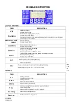
Page 15: ...y range 0 9999 Scan every 6 seconds with Total Stroke Total strokes number clear after power off adaptor plug out PULSE Pulse bpm during rowing Display range 0 30 240 WATT Show power value during training Display range 0 999 HRC Show percentage of heartbeat during target training Display range range 55 75 90 TAG ITEM DESCRIPTION Up Setting selection Increase resistance level Down Setting selection...

Page 16: ...lect Program mode and press ENTER toconfirm 2 Press UP or DOWN to select profile P1 P12 and press ENTER toconfirm 3 Press UP or DOWN to preset Target for RESISTANCE LEVEL TIME or Meters STROKES CALORIES and PULSE and press ENTER to confirm Time and Meters can t preset at the same time 4 Press START STOP key to start workout Press UP or DOWN to adjust resistance level 5 When preset workout value co...

Page 17: ...ER to confirm 2 Press UP or DOWN to set resistance level of each column and press ENTER tonext one Total column 16 3 Hold on pressing MODE to finish or quit setting 4 Press UP or DOWN to preset TIME or Meters STROKES CALORIES and PULSE and press ENTER to confirm Time and Meters can t preset at the same time 5 Press START STOP key to start workout Press UP or DOWN to adjust resistance level 6 When ...

Page 18: ... default value is countdown to 0 the electronic meter will be alerted by a beep and stop moving 7 Press START STAP to stop moving Press RESET to return to the main interface Recovery Mode 1 User must be wearing a chest strap When the pulse value is displayed on the computer press on the RECOVERY key 2 TIME shows 0 60 seconds and count down Computer will show F1 to F6 after count down to 0 to test ...

Page 19: ......

Reviews: