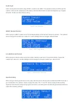
background image

PDM II

PDM II User Manual

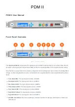
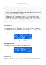
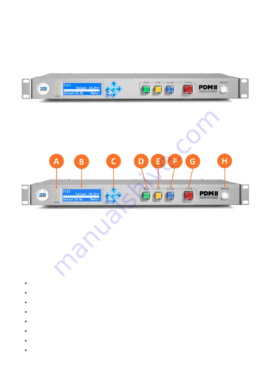
Front Panel Overview

Figure 1 - Front panel controls

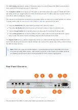
The Input Level Meter (A) monitors the signal going into PDM II’s processing circuit. As they follow the A/D 
converter in the signal path, they will accurately monitor the input regardless of the Input Sensitivity setting. 

Note that this is a peak meter to be used as a diagnostic tool for setting input levels; it does not display RMS 
voltage or a time-integrated level and is not intended to be a replacement for a more sophisticated loudness 
meter. 

Four dark LEDs: The input signal is below -36 dBFS.

One Green LED: The input signal is above -24dBFS.

Two Green LEDs: The input signal is above -18dBFS.

Three Green LEDs: The input signal is above -12dBFS.

Four Green LEDs: The input signal is above -6dBFS.

Top LED is Yellow: The input signal is above -0.5dBFS.

Top LED is Red: The input signal is above +0.5dBFS.

All LEDs are Yellow: The unit is expecting a Livewire input but not seeing a valid signal, or there is an 
internal error.

Summary of Contents for PDM II

Page 1: ...not display RMS voltage or a time integrated level and is not intended to be a replacement for a more sophisticated loudness meter Four dark LEDs The input signal is below 36 dBFS One Green LED The input signal is above 24dBFS Two Green LEDs The input signal is above 18dBFS Three Green LEDs The input signal is above 12dBFS Four Green LEDs The input signal is above 6dBFS Top LED is Yellow The input...

Page 2: ...o return to real time audio The blue Cough button F temporarily stops incoming audio from reaching the delay buffer The red Dump button G dumps the buffered audio or plays a pre recorded audio file when a guest caller or even the talent utters something objectionable that should not be aired The Bypass button H is used for emergencies or when you want to electrically remove PDM II from the signal ...

Page 3: ...a the front panel controls The front panel navigation cluster is made up of five buttons Navigation cluster Left Right Up and Down buttons for navigating through lists and adjusting values holding down an arrow will generally repeat the action Checkmark button for entering menus and confirming choices X button to Cancel and exit a menu without saving any changes To begin press the Checkmark button...

Page 4: ...will be merged into a single image so that all information can be displayed at once The full configuration menu is below the sections that follow will describe each sub menu Figure 2 Complete Configuration menu Audio Menu The Audio Menu is used to select and configure various audio I O parameters and values Note Some of the options displayed in the Audio Menu are contextual and will change dependi...

Page 5: ...vigate between fields Figure 3 AES67 receive address Livewire Receive Channel When using a Livewire audio source the receive channel is set here The up down arrows change the number by a value of 1 and the left right arrows change the channel number by a value of 100 Figure 4 Livewire receive channel screen Input Sensitivity When using an analog audio source this value should be set to the absolut...

Page 6: ... with heavily processed input content while higher settings may be necessary for content with very wide dynamic range Analog Output Level The Analog Output Level screen displays how the analog output level reflects digital audio levels within PDM II s processor With the setting as shown below 0 dBFS within PDM II will yield a 14 dBu analog output The output levels should generally be set to match ...

Page 7: ...e multicast address of the AES67 transmit channel is set here The up down arrows change the number by a value of 1 and the left right arrows navigate between fields Figure 10 AES67 Tx address Livewire TX Channel The Livewire channel number for PDM II s audio output is set here The up down arrows change the number by a value of 1 and the left right arrows change the channel number by a value of 100...

Page 8: ...mount of audio deleted when the Dump button is pressed The up down arrows set a value between 1 0 and 60 0 seconds in 0 1 second increments Figure 2 Dump size screen Note The Dump Size and Delay Size screens are not visible when the Dump Mode is set to OverKill Delay Size The Delay Size control determines how much delayed audio PDM II will store in its buffer The up down arrows set a value between...

Page 9: ...es will build the delay more quickly but may cause audible artifacts depending on the type of programming As a rule content with more density such as highly produced music will better tolerate higher speeds without audibly compromising the audio More sparse material such as speech will more easily reveal artifacts We recommend starting with the default value carefully listening to your on air audi...

Page 10: ...tomation system to play audio Build File The Build File menu allows you to choose which audio file will play out from PDM II s internal memory when building a delay using the Insert mode Figure 8 Build file screen Note PDM II can store multiple audio files in its internal library Files can be uploaded and managed on the page of the web based user interface Audio Files Note The audio files should b...

Page 11: ...eletes the objectionable audio and jumps ahead in time then immediately begins to rebuild its delay buffer OverKill This mode plays a pre selected file in place of the objectionable audio In this mode the delay buffer is maintained and does not have to be rebuilt OverKill File This menu allows you to select which previously uploaded audio file will play during a dump event when the Dump Mode has b...

Page 12: ... location Four specific U S time zones with and without Daylight Savings Time are included along with all internationally supported offsets from Greenwich Mean Time GMT Figure 1 Time zone screen Time and Date The current time and date can be set manually when NTP is not used The left right arrows change the field while the up down arrows change the value Figure 2 Time and date screen Note Having a...

Page 13: ... down arrows change the value Valid characters include upper and lower case letters numbers and space between characters Note that spaces at the end of a character string are automatically removed Figure 4 Password screen If there is no password the display will show a flashing Web UI Disabled message Note PDM II passwords are designed to prevent unauthorized access via the remote network interfac...

Page 14: ...es Setting it to Never will keep the display on continually although this is not recommended due to the finite life of the LCD backlight Figure 7 Screen saver screen Network Menu The Network Menu contains the controls necessary for configuring PDM II s two network ports Note that not all menu items will be visible with all configurations Figure 1 Network menu Networking Overview ...

Page 15: ...d DNS Disabled No No User specifies IP address mask gateway and DNS Disabled By default the Secondary port is disabled and the Primary port has DHCP enabled Separate Ports v Using a Single Port Generally speaking and when two separate Ethernet ports are available it is preferable to connect the Primary port to the dedicated Livewire or AES67 network and the Secondary port to the office network for...

Page 16: ...n be toggled on in the Secondary Net Enable menu Figure 2 Secondary DHCP enabled screen When the Secondary port is enabled it can be set to have DHCP enabled or disabled When disabled its fields for manually setting the IP address subnet mask and gateway are visible NTP Enable Menu NTP Network Time Protocol can be enabled or disabled in this menu Figure 3 NTP enable screen NTP Server Menu This men...

Page 17: ...rent draw of 200 mA The supply is protected by an internal self resetting thermal circuit breaker should the breaker trip power the unit off for several minutes to reset it Inputs require at least 6mA from the input common pin and the individual input circuit pin Outputs can carry up to 25 mA and up to 30VDC per channel between the output common pin and the individual output circuit pin If the out...

Page 18: ...e triggered or level sensitive Triggered or edge sensitive inputs cause something to happen when the input becomes active Level sensitive inputs cause a state to be true as long as the input is active The CueX and Bypass inputs are triggered all others are level sensitive Input functions include None No function assigned Build Front panel Build button Exit Front panel Exit button Cough Front panel...

Page 19: ...lows you to have input closure immediately cause and output closure with no delay This is useful for implementing or diagnosing end to end relay logic when connecting PDM II to other devices Pause Suspends delay or exiting when active GPIO Outputs Each of the five output pins can be assigned a PDM II function Figure 4 GPIO outputs GPIO outputs can either be triggered or level sensitive Triggered o...

Page 20: ...elay dump DelayEmpty Indicates the delay buffer is completely empty Muted Indicates the unit is currently muted Flag Applies to Flag 1 through Flag 8 functions See the GPIO Inputs section for a full explanation of Flags Util Applies to Utility 1 through Utility 4 functions See the GPIO Inputs section for a full explanation of Utilities StreamFail Indicates the currently selected digital input has ...

Page 21: ...librating its internal clock which may take a few minutes depending upon the connection and how much adjustment is required Sync PDM II s clock is synchronized with the remote NTP server Basic Operation In short the primary function of the PDM II is to create a buffer of delayed audio that ensures profanity or other objectionable audio doesn t make it to the air Creating this buffer is called buil...

Page 22: ... which makes the transition from Bypass mode seamless Figure 3 Ready screen Pressing the Build button begins building a delay and the length of the delay will increase as the buffer builds Figure 4 Delay building screen Building a Delay Begin by pressing the green Build button which will flash while the delay is building up The talent should start talking immediately Depending on how your system i...

Page 23: ...ng smoothly the Dump button will light The delay memory can hold more audio than is needed for a single dump event When it reaches a limit you ve previously set the Build button stops flashing while the Dump button remains lit You can choose how long PDM II takes to build a delay Choose a setting based on how quickly your talent talks how subtle you want the time manipulations to be slower speakin...

Page 24: ...his Overkill Mode The selects whether PDM II uses Normal or Overkill mode when you press the Dump button You can change this setting as needed for different program formats Controls Menu The same menu also lets you select which stored audio file will play during Overkill PDM II s Dump Size and Delay Amount automatically adjust to the length of the selected Overkill file For example if you want an ...

Page 25: ...on that the files have been created or the complete files are sent to the e mail addresses set up in your PD Alert System Instructions for setting up this list are provided in the of the Configuration menu in the web GUI PD Alert section Exiting Delay To exit the delay press the yellow Exit button If the Exit Mode is set to Compress PDM II will play any remaining audio using time compression subtl...

Page 26: ...on shows where PDM has smoothly deleted material from the on air program Note that we exaggerate and stretch the text to better illustrate how PDM II adjusts audio speed In actual use PDM II s functions are a lot more subtle and most listeners won t be able to tell they re in use They re also user adjustable so you can fine tune the sound to your programming and station s style Building and Dumpin...

Page 27: ...rmonic distortion or frequency limitations or rely upon deleting pauses in the audio As a result it can be used on audio with continuous energy such as music or live events with background crowd noise and will never degrade your talent s delivery Using lower speed numbers causes the least amount of tempo change and are usually imperceptible but take longer to fill the delay memory or return to rea...

Page 28: ... before the scheduled program time and is often used by studios feeding a network rather than a local transmitter Set the Build Mode to PreRoll and press Build The talent should begin talking earlier than program air time specifically by the same number of seconds as the Delay Size This early start will be heard in the studio only For example if you feed a network at 12 00 Noon and use a 10 second...

Page 29: ... by Rolling Out or Compressing Exit by Roll Out This is the traditional method of exiting delay not dissimilar to the method used by old fashioned tape delays The talent finishes speaking then presses Exit PDM II continues to play delayed audio at normal speed until the delay is empty then passes the incoming audio through to the output with no delay Note The COUGH button has no effect while exiti...

Page 30: ...oose a Speed appropriate for your talent s style of delivery so that listeners won t notice the time compression Hosts who speak very quickly usually sound better with lower Speed settings Quick Exit with Compressed Roll Out This mode is faster than using either the Compress or Roll Out modes by themselves To use it PDM II should be set to Compress mode The talent presses Exit and stops talking PD...

Page 31: ...word via the front panel then you will be required to set your password on the initial web page Enter the password twice click Set Password click OK on the dialog that appears and then continue with the instructions Once connected you will be prompted to enter a Name and Password Enter pdmweb as the user name and the password that you have set via the front panel or the initial web page Passwords ...

Page 32: ...ttp 10 11 12 100 81 To access unit B enter http 10 11 12 100 82 Because the ports operate together in pairs it is only necessary to specify the http port the WebSocket connection for HTML5 will follow along The browser will always contact the WebSocket at a port 5360 less than the web page s port Be sure to also set any necessary permissions in your firewall Front Panel GUI Page PDM II can be oper...

Page 33: ...ractive and the on screen buttons can be activated with a mouse click The following keyboard shortcuts are also supported The Left Right Up and Down keyboard arrow keys correspond to the front panel arrow buttons The keyboard Enter key corresponds to the green Checkmark button The keyboard Escape key corresponds to the red X button The letters B E C D and Y respectively correspond to the Build Exi...

Page 34: ...dresses of any additional PDM II s as desired click Add and enter the user name and password when prompted As many as 20 panels can be displayed at once The name of each PDM II as set in the Configuration menu will be displayed to help identify each specific unit Figure 4 Multiple mini windows Note The Mini Front Panels are displayed in the order in which you entered them once displayed they canno...

Page 35: ...t be used The name will be displayed on the Mini Windows when connecting with the web GUI It will also be used when creating log file names and PD Alert e mails Figure 1 PDM name Control Section By default PDM II boots in Bypass mode but this behavior can be changed from the Boot mode dropdown in the Control section Bypass Effectively connects the analog and AES3 outputs to their corresponding inp...

Page 36: ...e GPIO Livewire GPIO Section GPIOs can be controlled via Livewire by first checking the Enable box then entering a Livewire channel number or a valid multicast address You may also enter an IP address and port number such as 192 168 2 114 2 to reach out to another device on the network using a TCP connection sometimes referred to as snake mode as it creates a GPIO snake between the two devices Use...

Page 37: ...kets data to the stream Remote TCP port makes a TCP socket connection to the specified remote address and port and then adds any incoming data from those connections to the stream If the connection fails it will reconnect The Local TCP and Local UDP options will accept input from multiple devices the PDM II will merge all the incoming data into the delay stream With these options Stream A accepts ...

Page 38: ...e mails it does not require an incoming POP server Mail server address Enter a valid SMTP server address typically smtp yourdomain com With TLS disabled the default mail server port is 25 With TLS enabled it is 587 If your mail server uses a different port specify it by adding a colon and the port number after the address e g smtp yourdomain com 465 Mail server username Enter a valid e mail accoun...

Page 39: ... Enter the e mail addresses of people who should receive text only PD Alerts that is alerts that a Dump event has occurred but without the corresponding audio files which can be retrieved from the PDM II log files as needed For more than one recipient separate each address with a space Retain dump files PDM II purges old audio files to make room for new ones when more space is needed in its intern...

Page 40: ...s non PTP aware switches or both P2P calculates the delay between two slaved devices rather than the entire network It is typically more accurate and efficient than E2E PTP Clock Priority1 Priority 1 is the most significant of the six factors used by devices in the selection of a master clock Acceptable values range between 0 and 255 with lower values representing a higher priority The default val...

Page 41: ...D Alerts e mail log If you need to configure PD Alerts go to the configuration page Dump Archive Page Clicking on the Dump Archive tab lists all Dump files stored within PDM II The most recent file is shown first Files are built in pairs one for the studio audio that got deleted OffAir and one for what the listeners actually hear OnAir Clicking on any file name will play the corresponding audio th...

Page 42: ...h covers the dumped material with an internal audio file of the same length the OffAir file will be longer than the OnAir file In the unlikely event that PDM II has zero delay available when the Dump button is pressed and you are not using Overkill Mode both files will be identical in size and will contain only the pre and post Dump context audio Figure 2 OnAir v OffAir files ...

Page 43: ... maximum supported file size is 6MB Up to 150MB of audio can be stored in total Important The audio files should be stereo 16 bit WAV files with a 48kHz sample rate to match the sample rate of PDM II s internal clock and ensure proper speed and pitch during playback Utils Page The Utils tab is used to upload and select firmware versions to download logs when requested by customer support and to re...

Page 44: ... before the unit reboots Information Page Clicking on the Information tab provides an abundance of data about PDM II including audio networking and time format statuses hardware specific information and unique identification numbers This is a read only page and does not update automatically once loaded To see recent changes refresh the page manually Parallel Remote Control In addition to IP based ...

Page 45: ... Language Structure PDM II s serial remote control language is designed to be easily implemented from any terminal program by macros in most automation systems or by computer programming language Requests and responses are standard ASCII characters based on plain English using familiar PDM II front panel designations whenever possible Requests messages from the controller to PDM II consist of a nu...

Page 46: ...capital letters and must be sent exactly as shown Arguments include GPIO section Build Exit Cough Dump Bypass Cue 1 Cue 8 Flag 1 Flag 8 Variables include Depth Current audio delay length in seconds and tenths PeakInput Peak input level both channels in dBFS PeakOutput Peak output level both channels in dBFS TemperatureC or TemperatureF Current internal temperature in whole degrees Celcius or Fahre...

Page 47: ...P GUEST LF unknown command DUMP LF PDM II doesn t understand this instruction no action is taken Note 1 Help does not require an argument If you send help LF by itself it returns a list of valid commands If you specify any command as the argument it returns a brief explanation along with a list of the command s arguments For example if you send help down LF PDM II replies with down send Press sign...

Page 48: ...ig Muted LF tells PDM II to report any time either DUMP or MUTE has been activated Use All for EventName as a shortcut when you want to enable messaging for every PDM II event When PDM II receives any valid enable command it responds LF If a function is active when you enable its message PDM II reports its state immediately and then sends an updated report when the state changes For example if you...

Page 49: ...ommand The disable command turns off reporting of one or more output events and follows a similar syntax disable DumpTrig LF tells PDM II to stop reporting that DUMP has been activated disable DumptTrig Muted LF turns off reporting for both functions disable ALL LF turns off any message reporting PDM II responds to valid disable commands with LF Note The disable command affects only serial message...

Reviews: