13
5
Connecting
Block Diagram
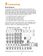
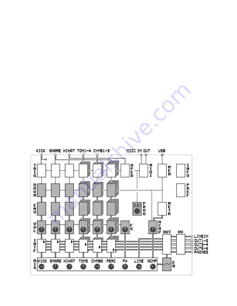
The DrumIt Five internal architecture is best described by the
organization of all pages and their function as shown in the block
diagram here below. It shows the signal flow from trigger input to
audio output (MIDI and other data signals are shown with dotted
lines). The stereo audio signal of each channel is always routed to
the mix bus and can also be routed to bus (pair) 1 to 8.
- 1+2, optionally routed to output 1 and 2.
- 3+4, always routed to output 3 and 4.
- 5+6, always routed to output 5 and 6.
- 7+8, optionally routed to the phones.
- Mix, optionally routed to output 1 and 2 and / or the phones.
There's also a submix bus which consists of a combination of mix
channels. The bus to output selection is made on the UNIT-OUT
page. See chapter 8 for detailed page descriptions.
Shaded pages are in kit mode, the other ones in unit mode.

