background image

8

2

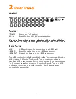
Trigger Inputs

KICK

Trigger on tip, current source for LED array on ring.

SNARE

Trigger on tip, trigger on ring.

HIHAT

Trigger on tip, sense amplifier for pedal on ring.

TOM1-4

Trigger on tip, trigger on ring.

CYMB1-3

Trigger on tip, switch detect for zone and choke on ring.

All trigger inputs have TRS input jacks. The trigger function on the 
tip contact is the same for all, while the function on the ring contact 
can differ. Please note that any pad can be connected to any trigger 
input jack. The function on the ring contact of the pad might not 
work as expected, but no damage will be done.

The SNARE and TOM inputs can be used to connect 5 additional 
triggers for a total of 15 independent trigger inputs. Use a split cable 
(Y cable) with a stereo TRS jack on one end to the trigger input, and 
2 mono TS jacks on the other end to 2 separate pads. Some pads 
may loose some of their functionality when connected this way. For 
example, the rim on a snare or tom pad will become inactive and 
position detect plus choke on a cymbal pad will be disabled.

Audio Inputs and Outputs

LINE IN

Stereo line level input for media players or instruments.

OUT1-6

Mono line level outputs with the ring contact to ground.

PHONES

Stereo headphones output (32 to 600 Ohm).

The LINE IN can be set to accept mono or stereo signals (see UNIT-
OUT page). In mono mode only the tip signal is used for both left 
and right, in stereo mode the tip is left and the ring is right.

The OUT1-6 outputs have the ring contact to ground. So for a 
balanced TRS to XLR cable, the XLR negative signal is grounded.

The PHONES output is independent of the other outputs. It can be 
used as 2 additional line level outputs for a total of 8 audio outputs. 
Use a split cable (Y cable) to obtain a separate left and right signal. 
Please note that the maximum signal level is two times (6 dB) 
higher than the line outputs. If the 7+8! bus with fixed level is 
selected for the headphones output (see UNIT-OUT page), the 
nominal signal level is matched to the OUT1-6 levels to accomodate 
an easy connection of all 8 outputs to an external mixer.

Summary of Contents for DrumIt Five

Page 1: ...DrumIt Five User Manual OS version 1 22...

Page 2: ...www 2box se Manual revision 2 2box and DrumIt Five are trademarks of 2box AB Sweden...

Page 3: ...3 0 Contents 1 Introduction 5 2 Rear Panel 7 3 Top Panel 9 4 Getting Started 11 5 Connecting 13 6 Files 15 7 Editing 17 8 Page Reference 18 9 Utility Functions 40 10 Addendum 42...

Page 4: ...0 C conditions keep the bottom and back free for air ventilation and don t use excessive force while handling the unit In short be careful just as one would be with other electronic equipment The inte...

Page 5: ...it just as easy as one would copy files to an external hard disk Triggers The fast and flexible trigger interface offers low latency and wide dynamic range Additionally depending on the type of pad di...

Page 6: ...choose between and these plus the tempo can be set individually for each kit To start a song with the right tempo the metronome can count in 1 or 2 bars and then stop PC Mac Editor The DrumIt Five Ed...

Page 7: ...ecting to a USB host MIDI IN Input for data from other MIDI equipment MIDI OUT Output for data to other MIDI equipment The USB version is 1 1 full speed 12 Mbits sec compatible with USB 1 1 and 2 0 ho...

Page 8: ...on a snare or tom pad will become inactive and position detect plus choke on a cymbal pad will be disabled Audio Inputs and Outputs LINE IN Stereo line level input for media players or instruments OU...

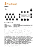
Page 9: ...s are assigned to them they trigger the rim sound on the snare or tom channels Pressing a channel button selects the channel and triggers the associated sound the button trigger level is programmable...

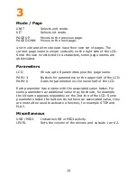
Page 10: ...s plus the page name PAR1 3 Buttons for parameters on the upper half of the LCD PAR4 6 Dials for parameters on the lower half of the LCD Each parameter has a name with the associated value below For s...

Page 11: ...CALIB once more to store the open position If the calibration is ok Done will be displayed otherwise NoChg appears indicating that no settings have been changed This might be because the range betwee...

Page 12: ...3 faders control the volumes for the effect input and accompaniment The mixer settings are common to all kits and are saved with the unit settings The individual drum channel volumes for each kit can...

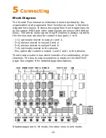
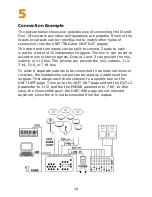
Page 13: ...ch channel is always routed to the mix bus and can also be routed to bus pair 1 to 8 1 2 optionally routed to output 1 and 2 3 4 always routed to output 3 and 4 5 6 always routed to output 5 and 6 7 8...

Page 14: ...be set to accept mono or stereo signals Output 1 and 2 can provide the mix submix or 1 2 bus The phones can provide the mix submix 1 2 3 4 5 6 or 7 8 bus To allow 8 separate outputs to be connected t...

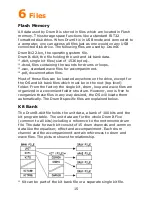
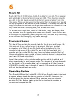
Page 15: ...the drive except for the OS and kit bank files which must be in the root top level folder From the factory the single kit drum loop and wave files are organized in a convenient folder structure Howeve...

Page 16: ...data for the drums and loops In this context drum refers to any instrument like tom cymbal percussion etc Each drum file holds all articulations for the complete instrument So a tom file can hold the...

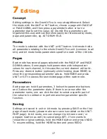
Page 17: ...values for each channel in this case the current channel will be lit Press any channel button optionally while holding down MORE to show the corresponding parameter values Hold MORE and press UNIT or...

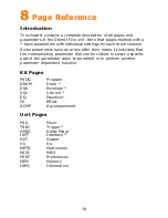
Page 18: ...ow after their name It indicates that the corresponding parameter dial can be clicked to select a specific part of the parameter value to be edited or to perform another parameter dependent function K...

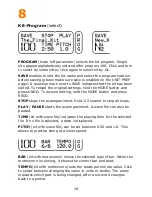
Page 19: ...he MORE button and press REDO STOP stops the accompaniment Hold 1 2 second to stop all loops PLAY PAUSE starts the accompaniment A wave file can also be paused TIME kit with wave file indicates the pl...

Page 20: ...s the kit and returns to program select The kit at the new program location will be overwritten MOVE new program location moves the kit and returns to program select The kits in between the current an...

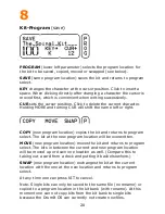
Page 21: ...the pitch of the sound The lowest pitch is 12 half notes one octave down the highest pitch is dependent on the sound encoding upto 4 half notes is common Click to switch between tuning in 100 cent ha...

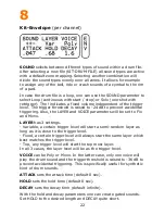
Page 22: ...YER and VOICE parameters will be set to Fix and Mono LAYER has 3 settings Variable a certain trigger level will start a semi random layer as long as it is close to the trigger level Fixed a certain tr...

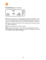
Page 23: ...Drum Note the channel direct out does not pass through the equaliser FX sets the effect send volume This is taken after the main volume so called post fader BAL sets the balance for stereo sounds VOL...

Page 24: ...ontrol click the MID dial and turn to sweep the frequency from 100 Hz to 10 kHz in 1 3 octave steps BUS selects the bus on which the equaliser is active either the Mix Sub or Drum bus The last one is...

Page 25: ...sec The Syn setting synchronizes the delay time with the tempo of the metronome Click to select Center Left or Right for the delay output FBK feedback sets the volume of the delay output going back to...

Page 26: ...type RATE sets the modulation speed it can be between 0 1 and 10 Hz DEPTH controls the flanger intensity it can be from 0 to 10 VOL sets the effect volume Note that the volume in the mix is affected...

Page 27: ...select the left chan as the music and the right chan as the click track or vice versa depending on the way the wave file is recorded This enables having both music and click in the mix eg to the phone...

Page 28: ...me signature Bars from 1 4 to 7 4 and 3 8 to 12 8 can be chosen The odd bars 5 8 and 7 8 have several formats The 1 4 bar is convenient when a single accent is sufficient TEMPO sets the beats per minu...

Page 29: ...l faders at the time with full names Click the parameter dials to directly select the 3 faders indicated above each dial VU meter shows the left and right signal level of the mix It s either located b...

Page 30: ...0 dB The maximum gain is 24 dB From 12 dB and upwards the threshold is increased to avoid stray triggering When the TYPE is Cym12 or 14 the GAIN parameter has an extra cup value selectable between Low...

Page 31: ...mall Finally fix it at a possibly higher open position which suits ones playing style MIDI selects between continuous controller 1 or 4 The CC value range can be set from 0 when open to 127 when close...

Page 32: ...e than one zone like cup bow edge and choke the additional zones are mapped onto consecutive higher notes Click to switch between note name and note number MIDI note 0 corresponds to C 1 and note 60 t...

Page 33: ...e a mix for recording or PA with just the drums and effect while still having all channels to the phones The channel volumes of the submix are the same as those for the mix and are set on the UNIT MIX...

Page 34: ...e at a fixed level see UNIT OUT 3 4 show the level of output 3 and 4 They always provide bus 3 4 at a fixed level 5 6 show the level of output 5 and 6 They always provide bus 5 6 at a fixed level PHON...

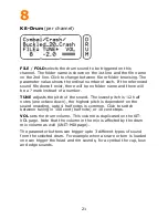
Page 35: ...st there will be no folder name and there will be a mark instead of a number TUNE adjusts the pitch of the sound The lowest pitch is 12 half notes one octave down the highest pitch is dependent on the...

Page 36: ...back note on off data THRU can be On or Off It selects if MIDI in data is passed on to MIDI out This allows a MIDI master to control the DrumIt Five plus additional MIDI instruments connected to Drum...

Page 37: ...off FAD selects the fader name to be edited turn to choose between fader 1 to 6 Click to set the cursor at the first character and turn to change it Click to increment the cursor position The assignm...

Page 38: ...the amount of files in all folders This is not the same as the amount of sound files as it also includes the OS files plus any other files FLASH is the Flash memory size in GB USED is the percentage o...

Page 39: ...39 8 Unit Information SERNR is the DrumIt Five serial number BOOT is the version of the boot program OS is the version of the operating system...

Page 40: ...or not recoqnized by the host computer the USB_Disconnected status will be shown If attached properly the status will be USB_Connected One can now copy files between the host computer and the DrumIt F...

Page 41: ...th earlier OS versions Reset To reset the system to factory default settings there are two possibilities Download the DrumIt dkit file from the 2box web site Connect the DrumIt Five with an USB cable...

Page 42: ...8 V AC external power supply Unit dimensions incl rubber feet and knobs width x depth x height 260 x 166 x 65 mm 10 2 x 6 5 x 2 6 inch 1 25 kg Glossary dB deciBell VU Volume Unit AC Alternating Curren...

Reviews: