background image

RU

UA

EN

КЕРІВНИЦТВО ПО ВИКОРИСТАННЮ  

КОМП’ЮТЕРНОГО КОРПУСА 

РУКОВОДСТВО ПО ЭКСПЛУАТАЦИИ 

КОМПЬЮТЕРНОГО КОРПУСА

COMPUTER CASE OPERATION GUIDE

2E GAMING VERTEX BLACK (2E-GI01B)

Summary of Contents for GAMING VERTEX BLACK

Page 1: ...RU UA EN COMPUTER CASE OPERATION GUIDE 2E GAMING VERTEX BLACK 2E GI01B...

Page 2: ...ini ITX 5 25 2 5 2 4 3 5 2 9 3 120 140 1x 120 140 2 120 140 240 280 360 120 140 240 280 3x 140 ARGB 6 pin 1x 120 ARGB 6 pin ARGB MOLEX 2xUSB 3 0 1xUSB Type C HD AUDIO MIC Power Reset LED HDD LED 2 VGA...

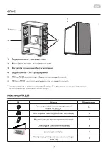
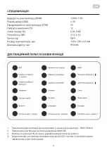
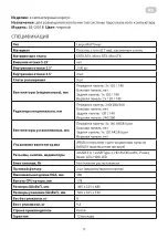
Page 3: ...3 UA 1 2 3 4 5 140 ARGB 6 120 ARGB SSD 2 5 24 4 3 8 1 MOLEX 1 4 5 1 6 2 3...

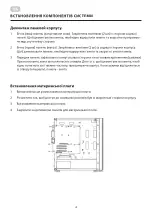
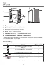
Page 4: ...4 UA 1 2 2 2 3 1 2 3 4...

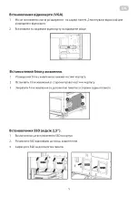
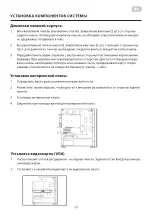
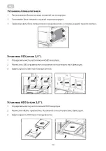
Page 5: ...5 UA VGA 1 2 1 2 3 SSD 2 5 1 SSD 2 SSD 3 SSD...

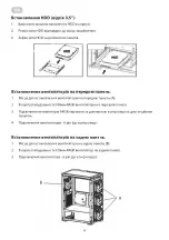
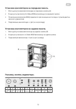
Page 6: ...6 UA HDD 3 5 1 HDD 2 HDD 3 HDD 1 2 3 140 ARGB 3 ARGB 4 6 pin 1 2 1 120 ARGB 3 6 pin A B...

Page 7: ...7 RU K A B C D E F G H K Power Button Reset Button Power LED HDD LED USB 3 0 USB Type C Headphone Jack Microphone Jack LED Button LED...

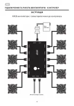
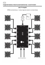
Page 8: ...8 RU ARGB LED...

Page 9: ...9 UA RPM dBA CFM V W 1200 10 26 55 12 0 26 0 48 3 12 5 76 6pin 120 x 120 x 25 450 1 2 3 1 FAN1 FAN10 2 MOLEX 3 ON 4 LED...

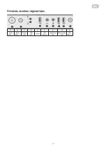
Page 10: ...10 UA 1 2 3 4 5 6 1 2 3 4 3 CR2025...

Page 11: ...ITX 5 25 2 5 2 4 3 5 2 9 3 120 140 1x 120 140 2 120 140 240 280 360 120 140 240 280 3x 140 ARGB 6 pin 1x 120 ARGB 6 pin ARGB MOLEX 2xUSB 3 0 1xUSB Type C HD AUDIO MIC Power Reset LED HDD LED 2 VGA 38...

Page 12: ...12 RU 1 2 3 4 5 140 ARGB 6 120 ARGB SSD 2 5 24 4 3 8 1 MOLEX 1 4 5 6 3 1 2...

Page 13: ...13 RU 1 2 2 2 3 1 2 3 4 VGA 1 2...

Page 14: ...14 RU 1 2 3 SSD 2 5 1 SSD 2 SSD 3 SSD HDD 3 5 1 HDD 2 HDD 3 HDD...

Page 15: ...15 RU 1 2 3 140 ARGB 3 ARGB 4 6 pin 1 2 1 120 ARGB 3 6 pin A B A B C D E F G H K Power Button Reset Button Power LED HDD LED USB 3 0 USB Type C Headphone Jack Microphone Jack LED Button LED K...

Page 16: ...16 RU ARGB LED...

Page 17: ...17 RU RPM dBA CFM V W 1 2 3 1 FAN1 FAN10 2 MOLEX 3 ON 4 LED 1200 10 26 55 12 0 26 0 48 3 12 5 76 6pin 120 x 120 x 25 450...

Page 18: ...18 RU 1 2 3 4 5 6 1 2 3 4 3 2025...

Page 19: ...m Front panel 240 280 360 Side panel non Rear panel 120 140 Top panel 240 280mm Included fans mm Front panel 3x 140 ARGB 6 pin Side panel non Rear panel 1x 120 ARGB 6 pin Top panel non Fan control ARG...

Page 20: ...antity pcs MB SSD 2 5 screws 24 Hex Screws to fix PSU 4 Copper Cylinder for MB 3 Cable tie for cable management 8 Remote control 1 Fan controller MOLEX 1 1 Front panel metal mesh 2 Side panel Tempered...

Page 21: ...y remove the panel 3 The front panel is fixed from the inside with plastic fasteners clips When pressed they are released from the holes In order to dismantle the panel it is necessary to pull its low...

Page 22: ...per position 3 Fix with hex screw from rear plate SSD installation 2 5 bay 1 Determine the location of the SSD in the case 2 Place the SSD in proper location 3 Secure SSD with screws HDD installation...

Page 23: ...s is controlled by a controller with a remote 4 Fans connection 6 pin to the controller Fan Installation on rear panel 1 Rear fan installation 2 1x120mm ARGB fan is installed in the case on the rear p...

Page 24: ...24 EN ARGB FAN CONNECTION DIAGRAM INSTRUCTION ARGB fan connection diagram Power supply LED light bar...

Page 25: ...l 2 Ice Green Ice Blue Green M M AUTO voice control model 3 Pink Purple Blue Brightness Brightness OFF 1 Connect the fans to the controller in the designated connectors FAN1 FAN10 2 Connect the contro...

Page 26: ...it before preparation of case for transportation 3 Avoid contact with moisture or water on the surface or inside of case to prevent corrosion of material 4 Utilization of case and it s packing in acco...

Page 27: ...2 1 2 3 4 5 6 12 __________________________________________________________________ 18 04073 0 800 300 345 044 230 34 84 390 55 12 www erc ua service...

Page 28: ...2 1 2 3 4 5 6 12 _____________________________________________________________...

Page 29: ...applicable law 4 The product is withdrawn from the warranty in case of violation by the consumer of the operating rules set forth in the instruction manual 5 The product is removed from warranty servi...

Page 30: ...ler stamp Date of the application Date of completion Cause of damage Coupon 3 Seller stamp Date of the application Date of completion Cause of damage Product information Product Model Serial number Se...

Reviews: