12
3. Description – Plug-In Boards
Warning:
GSM boards are always locked for one type of gateway. See table below for
more information:
Plug-in board
StarGate
BlueStar
BlueTower
CPU card StarGate
YES
NO
NO
CPU card BlueStar
NO
YES
NO
CPU card BlueTower
NO
NO
YES
AUX card StarGate
YES
YES
YES
AUX card BlueStar
YES
YES
YES
AUX card BlueTower
YES
YES
YES
PRI card StarGate
YES
YES
YES
PRI card BlueStar
YES
YES
YES
PRI card BlueTower
YES
YES
YES
GSM card StarGate
YES
NO
NO
GSM card BlueStar
NO
YES
NO
GSM card BlueTower
NO
NO
YES
12HP VoIP card
YES
YES
NO
4HP Thin VoIP card
YES
YES
YES
3G two channel card StarGate
YES
NO
NO
3G two channel card BlueStar
NO
YES
NO
3G two channel card BlueTower
NO
NO
YES
3.1. CPU Board
3.1.1. Board Description
The CPU board contains a powerful processor system controlling the whole system. The
board is designed on a 4-layer PCB of the size of 160x100mm. A simple serial interface COM1,
an Ethernet connector (10Base-T), and 5 board status LED indicators are located on the front
panel.
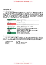
PWR LED
indicates board supply (LED is green in case of PRIGW)
INIT LED
indicates board initialization or error status
MEM LED
indicates call memory full (not shining=empty memory,
blinking 1:1 memory is 50% full, shining = 100% full
memory
LINK LED
indicates connection to Ethernet
ACT LED
indicates activity via Ethernet
3.1.2. COM1 Serial Interface Parameters
The COM1 interface is used as a local port for temporary connection of a PC (terminal) for
installation and servicing purposes and permanent connection of the SMS server (supervision
PC). It allows to provide local monitoring, configuration, tracing and firmware upgrade.
Transmission rate
57.6 kBd
Bit format
start, 8bit, stop (no parity)
Signals RXD,TXD,RTS,CTS,GND


