7
2. Basic Installation Instructions
This chapter describes the basic connection of the GSM Gateway that can be made in a few
minutes. All you have to do is to connect an antenna, the power supply cable and telephone
line, insert your SIM card and the GSM Gateway is ready to work.
2.1. Proper Location
•
The
ATEUS
®
- GSM GATEWAY COMPACT is a transmitter in principle. You must comply
with the local regulations and laws in your country pertinent to usage of mobile phones and
transmitters!
•
The
ATEUS
®
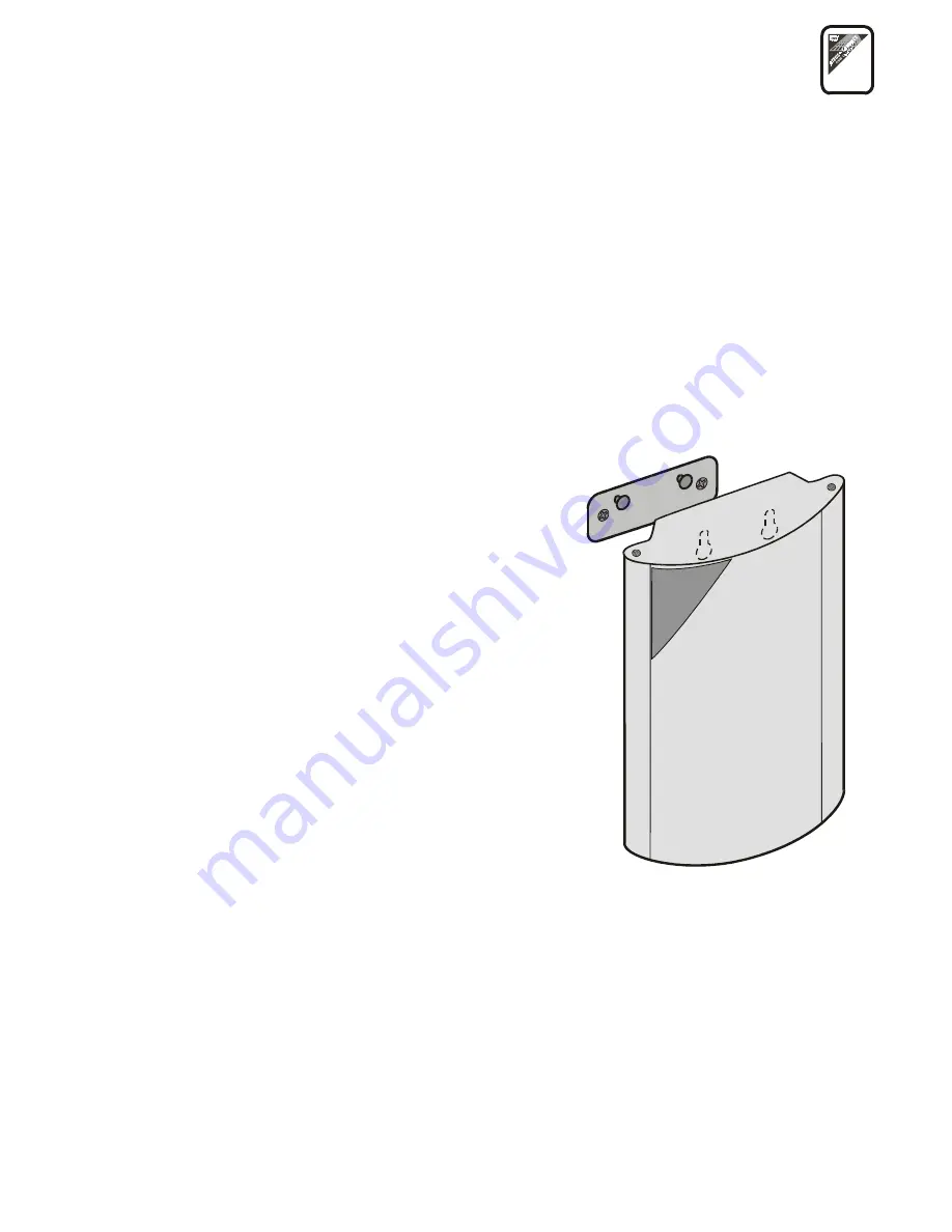
- GSM GATEWAY COMPACT is designed for vertical mounting. For the
required working position see Fig.1.
•
The GSM Gateway may be operated in a position other than vertical (on a desk, e.g.) for a
short time only – for quick maintenance testing, for example.
•
For the acceptable range of operating temperature and humidity refer to the “Technical
Parameters”.
•
The GSM Gateway may not be operated at places
exposed to direct solar or heat radiation.
•
Exceeding the acceptable operating temperature
does not have an immediate impact on the GSM
Gateway function, but may result in accelerated
ageing and lower reliability.
•
The GSM Gateway is designed for indoor use. It
must not be exposed to rain, water, condensed
moisture, fog, etc.
•
The GSM Gateway must not be exposed to corrosive
gas, fumes of acids or solvents, etc., or corrosive
liquids, during cover cleaning, for example.
•
The GSM Gateway is not intended for use in high-
vibration locations such as means of transport,
machine rooms, etc.
•
The GSM Gateway should be located with respect to
the GSM signal quality.
•
A free space should be left over and under the GSM
Gateway for cables and flowing air that removes heat
produced during the operation.
Fig. 1.:
GSM Gateway Working Position
Summary of Contents for ATEUS 501101E
Page 2: ......
Page 35: ...33 5 4 11 Remote Supervision Establishing Flow Chart ...
Page 56: ......
Page 57: ... 2002 2N TELEKOMUNIKACE a s Prague DR 972 v 1 33 ...


