


2N TELEKOMUNIKACE a.s., www.2n.cz
121/377
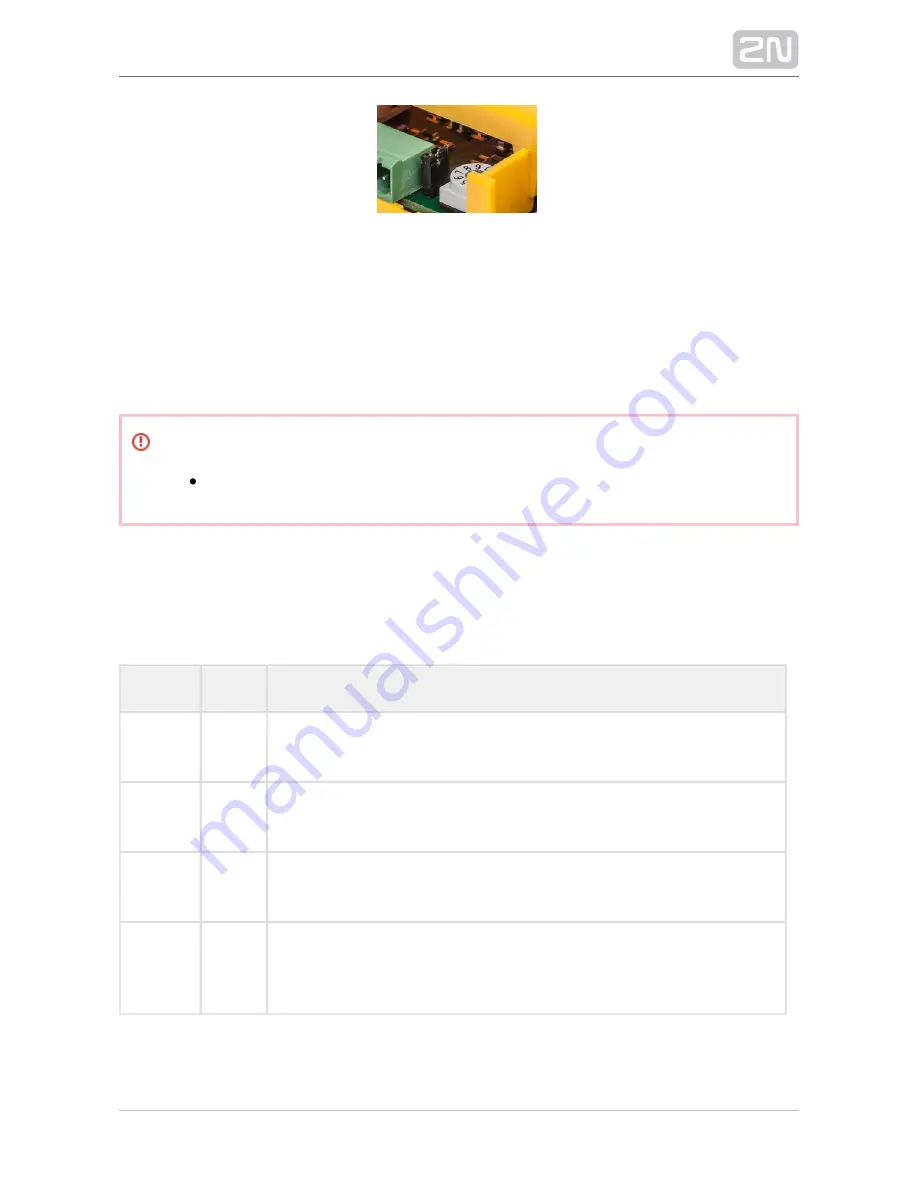
Termination Resistance Off
Address Setting
Use a 10-pin rotary switch 0–9 (see the figure above) to set the I/O Module address
for a lift. Set 1–8 like the shaft number for the splitter (set 5 for lift 5, e.g.).
Warning
Do not set address 0 and 9 to avoid system error.
LED Indicators
The I/O Module is equipped with ten LED indicators: two I/O Module status signalling
LEDs, four input status signalling LEDs and four output status signalling LEDs. Refer to
the table for details.
Name
Colour
Description
OK
Green
If everything is OK, the power supply and bus are connected, the I/O
Module is communicating with the CU, the LED is flashing.
ERR
Red
If the red LED is on, the bus is not connected or there is an address
collision with another I/O Module in the system.
Logic
Input 1–4
Orange
This LED is on when the given input is active, i.e. nominal voltage for
detection of logic 1 is detected on it.
Logic
Output 1–
4
Orange
This LED is on when the given input is active, i.e. the given relay is closed.
Summary of Contents for Lift8
Page 1: ...www 2n cz 2N Lift8 Communicator for lifts User Manual Firmware Version 2 3 1 ...
Page 28: ...2N TELEKOMUNIKACE a s www 2n cz 28 377 Indication Elements ...
Page 40: ...2N TELEKOMUNIKACE a s www 2n cz 40 377 Examples of Connection ...
Page 70: ...2N TELEKOMUNIKACE a s www 2n cz 70 377 ...
Page 95: ...2N TELEKOMUNIKACE a s www 2n cz 95 377 ...
Page 136: ...2N TELEKOMUNIKACE a s www 2n cz 136 377 User name Admin Password 2n ...
Page 202: ...2N TELEKOMUNIKACE a s www 2n cz 202 377 Connection two cabin lift ...
Page 210: ...2N TELEKOMUNIKACE a s www 2n cz 210 377 ...


