14
15
2VV.
Creating innovative solutions for you and your business since 1995.
ver.5 5-05-20
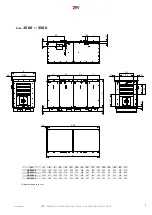
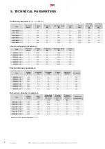
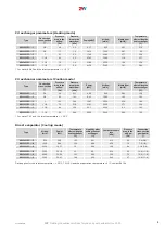
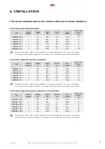
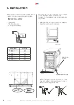
MLKR/S-400250-04N1-0
MLKR/S-450400-04N1-0
MLKR/S-500500-04N1-0
MLKR/S-700500-04N1-0
MLKR/S-700500-04N1-0
MLKR/S-1000500-04N1-0
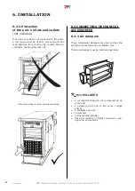
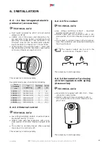
Install one dampers approx. 2 m the fresh air-suc-
tion neck of the duct, then install another damper
on the exhaust duct, approx. 2 m from the neck.
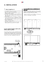
Connect servomotors to corresponding terminals
in the casing of the control unit. See chapter Co-
nnecting wiring and electrical accessories
Set the damper to a completely closed position if
the unit is off and to a completely opened position
if the unit is running. Setting the damper to a dif-
ferent position may damage the unit.
6.4. CONNECTING ELECTRICAL
ACCESSORIES
ATTENTION!
● Before any intervention in the ventilation
unit, the main power switch must be off!
● The ventilation unit´s electrical wiring must co
-
rrespond to a layout designed by a professional
electrician. The electrical wiring must be done
by a person authorized to perform electrical in
-
stallations. It is necessary to follow all instruc
-
tions in this manual and to comply with local
laws and regulations.
● The wiring diagrams depicted on the product
take precedence over diagrams in this manual!
Before connecting the wiring, make sure that
terminal indications match the diagram. If in
doubt, contact the supplier and do not connect
the unit!
● If the product is connected to other then original
control system, contact the supplier of such sys
-
tem for the wiring diagram of individual controls.
● The unit must be connected to the mains using
a heat-protected rigid insulated cable with the
cross-section that corresponds to local regulati
-
ons.
● To maintain the electrical protection, all cables
must fit in the holes on the sides of the control
unit casing.
● Any interventions or modifications of the inter
-
nal wiring of the unit are prohibited and lead to
loss of warranty!
● The unit´s correct operation can only be guaran
-
teed when original accessories are used.
● If it is necessary to install a sensor or a regulati
-
on component in the unit or on its casing, please
consult its location with the unit manufacturer
(or with its representative).
6. INSTALLATION
Types of rectangular dampers
Types of rectangular dampers
HR95-080..-..-....
HR95-150..-..-....
HR95-250..-..-....
HR95-350..-..-....
HR95-450..-..-....
HR95-550..-..-....

