background image


Page 104 

MAXX-2400HD Owner’s Manual 

Determining the Condition of the RAID Array 


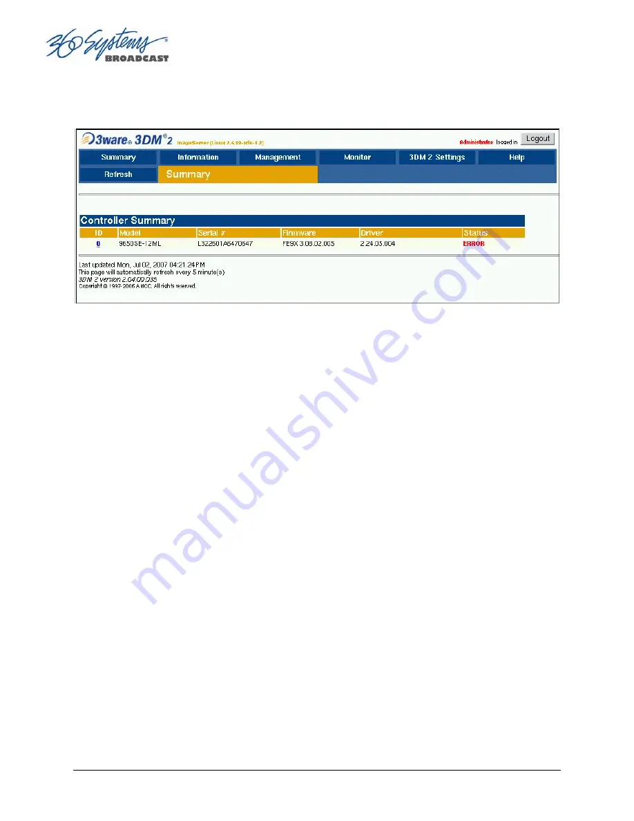
Figure 46 - RAID Array Condition Screen 


To replace a failed drive in the RAID control utility, perform the following steps.  The above 
screen should appear. 


Login as ADMINISTRATOR. 


Note the ERROR STATUS on this Summary Screen. 


If an error condition is indicated continue to next page.  

Summary of Contents for MAXX-2400-HD

Page 1: ...O P E R A T I O N S manual ...

Page 2: ...XX 2400HD High Definition Video Server P N 700 119 000x Operations Manual Rev 9 April 2012 Software Version 1 08 561 Copyright 2012 360 Systems All rights reserved Printed in the United States of America ...

Page 3: ...Page 2 MAXX 2400HD Owner s Manual Changes in this revision Add top panel removal instructions for TST chassis Correct GPIO pinouts and schematic Remove reference to unsupported file format ...

Page 4: ...cations for 360 Systems Servers 16 Accessory Information 17 Installation___________________________________________________________ 18 Unpacking 18 Important Installation Notes 19 System Cooling 19 Power Conditioning 19 About Server Software 21 Rack Mounting 22 Mounting an Audio Module AXP 3 AXP 4 or DXP 1 22 Mounting the Control Module CXP 22 Connecting the Monitor Mouse and Keyboard 23 Installin...

Page 5: ...version 41 Setting VANC Line Selections 42 Selecting a Time Code Source 42 Beginning Recording 42 Making a Crash Recording 43 Making a Named Recording 43 Monitoring a Recording Source with E E Mode 44 Playing a Clip from the GUI 46 Beginning Playback 46 Looping a Clip 46 Pausing a Clip 46 Ejecting a Clip 47 Using Jog 47 Using Go To Frame and the Frame Locator 47 Using Fast Forward Rewind 47 Slow M...

Page 6: ...mum Number of Items to Keep 65 Enabling As Run Logging 65 Viewing Editing and Archiving Playlists 65 Editing Playlists 65 Removing Clip from a Playlist 65 Removing Clips Above or Below the Selected Clip 66 Inserting HOLD Into a Playlist 66 Appending a Playlist FILE APPEND 66 Changing Duration of Clips in Playlist 66 Mapping GPO to Playlist Events 67 Mapping GPI to Control a Playlist 68 Advanced To...

Page 7: ...ing the Condition of the RAID Array 104 Displaying the Alarm Log of the Raid Array 105 Checking Status of the Drives 106 Removing the Degraded Drive from the RAID Unit 107 Rebuilding the RAID Array 108 Replacing Hard Drives 109 RAID Controller Settings 110 Multi Channel Audio 111 Audio Input Output Modules 111 DXP 2 Digital Audio Module 111 DXP 2 Technical Specifications 112 AXP 3 Analog Audio Mod...

Page 8: ...__________________________________________ 130 Serial Command Protocols 130 VDCP Command Table 130 P2 Serial Command Table 132 Odetics Protocol 133 Appendix C _________________________________________________________ 136 Technical Specifications 136 Keyboard Shortcuts 137 Appendix D _________________________________________________________ 138 Playlist Management Detail 138 Appendix E_____________...

Page 9: ......

Page 10: ...me that introduce new product features or improve the performance of the product When such revisions are shipped as a CD ROM printed operational notes are included When revisions are introduced in the course of product production an updated Operations Manual will be shipped with new servers The title page of an Operations Manual indicates its revision number which should always match the software ...

Page 11: ...void personal injury or equipment damage Only qualified personnel should perform installation and service Refer to appropriate sections of this product manual for instruction Contact 360 Systems Customer Support for further explanation or to clarify any uncertainty Disconnect the power cord before removing the cover Personal Injury Precautions To avoid electric shock do not operate this product wi...

Page 12: ...creen user interface Product Registration Important As the owner of new capital equipment you will want to take advantage of product information enhancements upgrades or notifications issued by 360 Systems Send in your Warranty Card so 360 Systems can remain in contact with you Mail or fax it to 360 Systems offices in the USA at the address given below Product Improvements and Upgrades 360 Systems...

Page 13: ...mats are available with MAXX 2400HD For surround sound eight channels of embedded audio are included 2 Optional multi channel audio modules provide 8 channels of AES EBU digital audio Model DXP 1 and either 4 or 8 channels of 4 balanced analog audio Model AXP 3 and AXP 4 MAXX 2400HD s versatile video and audio I O personality is unique among HD servers and guarantees a seamless fit in existing fac...

Page 14: ...vers and its easy to edit I frame format is accepted by an increasing number of NLEs The MAXX 2400HD runs at a wide range of video rates making it an excellent choice for production broadcast and even high quality projection Audio Features MAXX 2400HD provides most standard professional audio formats making it an easy fit in a new facility Eight embedded audio channels are standard equipment for e...

Page 15: ...ng system monitoring or play to air File Transfers over Gigabit Ethernet The MAXX 2400 goes beyond just base band connections for video and audio File transfers over Gigabit Ethernet allow the transfer of video content across the room or across the country at high speed and low cost With Ethernet switches and broadband connections the server s design enables low cost networking of broadcast operat...

Page 16: ...ander available AXP 4 Channels 5 8 Optional 8 channel AES EBU digital audio expander available DXP 1 12 Terabyte internal RAID 6 drive array for 240 hours of storage Slow Motion playback forward and reverse Key and Fill playback Targa file import via Ethernet MOV file import and rendering Serial control via VDCP BVW or Odetics protocols Compatible with leading broadcast automation systems FTP tran...

Page 17: ... and Forward Temporary storage for subsequent delivery Commercial Insertion Playout under automation control Instant Replay Hot Key playback of sports plays news clips stills and graphics Sports Shows and Events Slow motion playback player bios graphics promos Game Shows Prizes graphics animations promos Talk and Variety Shows Promos teasers intros outros graphics animations Award Shows Nominees c...

Page 18: ... 4 dBu balanced on XLR connectors Redundant power supply 3 88 mm height Requires AXP 3 DXP 1 Multi Channel Digital Audio Module optional Provides 8 AES EBU digital audio outputs for each of 4 video streams and 8 AES EBU inputs on XLR connectors Redundant power supply 3 88 mm height Maintenance Spares 360 Systems is committed to keeping your server on air Having spare parts on hand in the event of ...

Page 19: ...he MAXX 2400HD server weighs more than 90 pounds 40 kg Always use safe two man lifting techniques when handling it Package Contents Confirm that all items on the packing list have been received Contact 360 Systems if any item is missing 9 MAXX 2400HD server 9 Keyboard 9 2 Button Scroll Mouse 9 Software CD ROM backup copy 9 Remote Workstation Software CD 9 CXP serial control and GPI module 9 CXP in...

Page 20: ...ify that the HVAC system is not on a timer that can shut off on weekends or holidays What procedures are in place to protect the equipment when the HVAC system fails Power Conditioning It is good practice to operate an on air video server from an Uninterruptible Power Source or UPS All utility power systems experience occasional transient events including brownouts and dropouts which are capable o...

Page 21: ...put even when no conversation is taking place You may have experienced the effect of a cell phone interfering with a common desk phone placed nearby Carrying a cell phone into a machine room where it is in close proximity to broadcast equipment and its associated wiring is unwise Cell phones can interfere with serial control commands video synchronization and in some cases can crash the CPU in equ...

Page 22: ...ihood of static discharge About Server Software The MAXX 2400HD is shipped with its application programs and operating system installed The first time that it is started it must be connected to a keyboard monitor and mouse The server will ask you to accept the Software Licensing Agreement before it will operate This screen will only appear during the initial startup Refer to the Maintenance chapte...

Page 23: ...orth America Retract the front panel Tighten the front panel access screws Cables attached to the rear of the MAXX 2400HD should be supported Do not suspend substantial cable weight from the server Mounting an Audio Module AXP 3 AXP 4 or DXP 1 An optional multi channel audio module may also be rack mounted above or below the MAXX 2400HD on the front or rear of the rack Four elongated screw holes a...

Page 24: ... switched away from it When first powering up the MAXX 2400HD use only the supplied keyboard and mouse directly connected Then test the KVM switch system that will be used thoroughly before installation is completed Occasionally some KVMs will cause the mouse to stop responding or to behave erratically Mouse operation can be reset by the keyboard sequence Control Alt F12 the screen will go black f...

Page 25: ...ng power to the MAXX 2400HD Figure 2 Rear Panel Detail Rear Panel Connections to the MAXX 2400HD Server Mouse Keyboard USB CXP Interface Connector RS 232 Serial Port do not connect VGA Monitor NET 1 Gigabit Ethernet NET 2 not used Channel 1 and 2 HD SDI Inputs bi directional Channel 1 2 3 4 HD SDI outputs Channel 1 2 3 4 CVBS monitoring outputs Channel 1 LTC Input Channel 2 LTC Input LTC Output Ge...

Page 26: ... may be selected by means of the On Screen user interface and recorded as a time code reference This input may be selected by means of the On Screen user interface and used as a start time reference Note that time code is not actually recorded the time code read at the start of recording is captured When the clip is played back the time code in display VITC and LTC outputs starts from the captured...

Page 27: ...rt keyboard and mouse operation but it is still recommended to use PS 2 devices Currently a PS 2 keyboard is required for update operations using a USB drive as the limited operating system on the USB drive does not support USB keyboards Power Switch not shown in Figure 2 Shutdown the system only by momentarily pressing the front panel power button or through the SHUTDOWN command on the On Screen ...

Page 28: ... Figure 3 Be certain it is properly connected before applying power Connect Audio Module Here Figure 3 Audio Module Connection to MAXX 2400HD Control Module CXP Connections The CXP Module provides connections to the server s serial ports and its GPI interface using a 68 pin cable Connect it between the back of the CXP module and the CXP port on the back of the server Note that there are two cables...

Page 29: ...nt replay and edit control employ BVW or Odetics protocol Figure 5 CXP Module Connectors GPI Control The MAXX 2400HD provides twelve GPI inputs for control of machine functions which appear on two 25 pin GPI connectors This General Purpose Interface can be connected to switch contacts or to an open collector transistor output GPI inputs are programmable and can provide machine control such as PLAY...

Page 30: ...hen Shutdown then select either Shutdown to begin an orderly shutdown or Full Restart to do an orderly shutdown and restart without a full power down Alternatively momentarily pressing the front panel power button will cause the system to begin an orderly shutdown The server will acknowledge the button press with an audible beep and the front panel lights will begin to flash together Any operation...

Page 31: ...ns of all channels will operate immediately without first selecting a window to activate it Channel 3 is active in the illustration above indicated by its blue title bar When using key commands the active window is the only transport that will respond Use the CTRL TAB key combination to change the active window in rotation or use the mouse to activate the desired window by clicking anywhere in it ...

Page 32: ...ain System Configuration dialog See page 51 Windows Menu Choices in this menu change the way the windows are displayed Use the CTRL TAB key combination to change the active window in rotation or use the mouse to activate a specific window Cascade Arranges all open windows so that they are overlapping but offset It is useful as a starting point to rearrange the windows This choice is especially use...

Page 33: ... GENLOCK VIDEO INPUT DETECTED and TIME REMAINING PERCENT FULL Messages such as CONNECTED TO HOST or CONNECTION TO HOST REFUSED are also displayed as diagnostics Error and status messages from the RAID system can also be displayed here Channel 1 and 2 can Record or Play video content Channels 3 and 4 only play content All channels may be used at the same time Each channel can be controlled in two d...

Page 34: ...channel These operate in familiar VTR fashion Figure 7 Transport Channel View Transport Menu Bar There are two menus File and Options File Menu New Channel 1 and 2 only Opens the Clip Navigator to allow naming of a new clip then prepares channel 1 or 2 for recording See page 37 Key Command Ctrl N Open Opens the Clip Navigator to allow choosing a clip to load into the transport Key Command Ctrl O S...

Page 35: ...Close box in the upper right corner of the window Note that this will not stop playback or eject a loaded clip Options Menu This menu contains two selections Take Control Takes control of the video channel from another user the Serial Control a Remote Workstation or if you are using a Remote Workstation possibly the local GUI This item is grayed out when the window has control Key Command Ctrl T C...

Page 36: ...enu Bar There are two menus File and Options File Menu Open Opens the Clip Navigator to allow choosing a clip to load into the transport Key Command Ctrl D Append Opens the Playlist Selection dialog to allow choosing a Playlist to Append to the currently loaded list This can be done while playing to allow continuous playback of new Playlists See page 66 Save Saves an edited Playlist using its exis...

Page 37: ...ad another saved list Key Command Ctrl N Close Closes the Playlist window This has the same effect as the Close box in the upper right corner of the window Note that this will not stop playback or eject a loaded list Options Menu This menu contains two selections Take Control Takes control of the video channel from another user the Serial Control a Remote Workstation or if you are using a Remote W...

Page 38: ...tput is synchronized to the input as well so it is not possible to time the E E output to gunlock Setting the Video Sync Source To use with a genlocked system select External Sync using the GUI as follows A From the main menu bar select EDIT CONFIGURE Select the TIMING option The screen of Figure 9 appears B Select EXTERNAL as the sync source C Check that the front panel GENLOCK LED is now illumin...

Page 39: ...is takes at least 12 seconds so the change should not be performed on air Figure 9 Selecting Video Format The MAXX 2400HD must be set to operate in one format at a time it does not play mixed video formats when the video format is changed the only files visible on the GUI will be those recorded in the currently selected video format Files in another format will become visible when the server is pl...

Page 40: ...ary set Channel 1 and or Channel 2 to the Transport View Click FILE TRANSPORT in the Playlist View to switch to the Transport View Setting the Video Bit Rate Select OPTIONS CONFIGURE from the Channel 1 Transport Window The Dialog box in Figure 10 appears In the window enter the desired Video Bit Rate in Megabits sec not to exceed 125 Alternatively use the up down arrows to set a number Click APPLY...

Page 41: ...from the Channel 1 Transport Window Refer again to Figure 10 Channel Configuration Dialog Under TRACK ARM Check AUDIO if recording audio is desired All eight tracks are recorded Click APPLY or OK Setting an Audio Delay Time Audio tracks can be offset from video in 1 millisecond increments up to one second The setting is per channel and non volatile It applies to playback only not recording You mus...

Page 42: ...e as with wild audio or 44 1K audio Click APPLY or OK Bit for Bit Recording Playback Dolby E Dolby Digital AC 3 or other forms of compressed audio require that on playout the data stream be identical to the original Do not use the audio sample rate converters when working with these encoded audio formats Further the Dolby encoder must be supplied with the same video reference as the HDSDI input to...

Page 43: ... Select OPTIONS CONFIGURE from the Channel 1 Transport Window The Dialog box in Figure 10 appears The default Time Code Source is MANUAL Alternatively ATC VITC time code may be selected For MANUAL enter a time value in the window for the first frame of the recording Use the HH MM SS FF format It is not necessary to enter the colon between digit pairs Click APPLY or OK Beginning Recording When the ...

Page 44: ...ill not enter into the name field when typed They include and A list of existing clips will appear in the large window and can be used as a name reference when creating new clip names C The Channel 1 transport Window will display the words IDLE CUEING for two seconds or less When ready to record the Channel 1 Transport Window will display IDLE READY Note File naming is case sensitive Upper case le...

Page 45: ...nnel 1 and Channel 2 Record Play window It allows the input signal to be monitored from the server output E E Mode toggles automatically as described below but can also be switched manually at any time When a new clip is created for recording the input source is automatically switched ON to the output an E E connection When a clip is opened for play on Channel 1 or 2 E E monitoring is switched OFF...

Page 46: ...mation controllers may send E E ON and E E OFF commands to override the automatic operation Note that when in E E mode the video outputs are not timed to the genlock signal This will not be noticeable when connected directly to a monitor However there may be timing offsets when feeding timed routers or switchers The symptoms of this will vary depending on the particular equipment including horizon...

Page 47: ...by clicking on the folders 3 Select the clip to be play by double clicking it 4 When the Transport Window indicates Idle Ready the clip can be played by clicking PLAY Figure 14 Channel 1 Clip Navigator in Open Mode Looping a Clip Clicking on the LOOP checkbox in the Transport View will cause a clip to loop until LOOP is unchecked or until STOP is clicked LOOP may be checked or unchecked before or ...

Page 48: ...mes minutes and seconds and frames or hours and minutes and seconds and frames You can type the colons but they are not required Press Enter when done The video will jump to the specified frame if it exists and the Destination Field will become selected again to allow another location to be entered Using Fast Forward Rewind F F Fast Forward and REW Rewind buttons transport program material at high...

Page 49: ... slider represent 2X 1X maximums The Shuttle control slider works in three basic ways Snap Back to still Hold Speed and Mouse Wheel In Snap Back operation click and drag the slide control to change speed Releasing the slider bar will let it snap back to zero speed or still For Hold Speed operation position the cursor over the slider control scale not the slider arrow and click the left mouse butto...

Page 50: ...fter the recording begins Open the recording on either Channel 2 or 3 by selecting the clip name from the FILE OPEN menu A recording must be 3 seconds long before it will appear in the clip list Use the transport controls to select and mark the In and Out Points as desired Without un checking Edit select FILE SAVE AS enter a new clip name and click Enter A new clip is created that will play only b...

Page 51: ...total running time TRT of the current clip TRT is defined as the difference in the time codes between the first and last frames plus one For example if the first frame of the clip is 00 00 00 00 and last frame displayed at the end is 00 00 01 15 the reported duration will be 00 00 01 16 With 59 94 Hz drop frame time code the true play duration may not be the exact numerical value of Mark Out Mark ...

Page 52: ...he Main GUI Window Each individual server channel can also be given a name To assign a name to the server or transport channels click EDIT CONFIGURE NAMES from the main menu pulldown The screen of Figure 15 is displayed Use the keyboard to type in a name for any of the selections Names can be up to 31 characters in length Spaces digits and other non alphanumeric characters may be used Click APPLY ...

Page 53: ...r System Fault NO GENLOCK No genlock NO VIDEO INPUT No video at the selected input PLAYLIST Control GPO via playlist To program a GPO output select EDIT CONFIGURE GPO The screen of Figure 16 is displayed GPO 1 through 12 are triggerable outputs The checkboxes to the right of each selection represent channel 1 2 3 and 4 GPO 9 is shown with the trigger option pulldown expanded 1 To activate one of t...

Page 54: ...Playlist Mode Navigate to clip above currently selected clip SELNEXT In Playlist Mode Navigate to clip below currently selected clip STOP Stop a clip To program a GPI Input select EDIT CONFIGURE GPI Figure 17 will display the screen GPI 1 through 12 are programmable inputs The checkboxes to the right of each selection represent video channels 1 2 3 and 4 GPI 9 is shown with an expanded pulldown fo...

Page 55: ...etwork communication settings Click EDIT CONFIGURE NETWORK The screen of Figure 18 is displayed Figure 18 Network Configuration Screen The server is shipped with a default network Host Name and IP Address Qualified network engineers may change these configurations to suit your specific network environment Factory defaults for networking are Network Disabled Use DHCP Disabling the Network X This se...

Page 56: ...dit1 mydomain com All other manually configured addresses must be properly formatted IP addresses Saving Network Configuration Click on OK APPLY or CANCEL to accept or abandon new entries The IP address of the system is displayed in the upper left corner of the GUI at the end of the main window title The server is designed to be used in a private dedicated video network A firewall must be used in ...

Page 57: ...our geographic location or time zone Use the scroll bar as necessary and then click on the desired value Set the TIME and DATE by clicking on the Time Date field and navigating the clock and calendar Check Automatic Updates to enable automatic updates using the Network Time Protocol NTP Refer to Network Time Protocol on page 86 Note A System Restart is required for a Time Zone change to take effec...

Page 58: ... Rename from the pop up menu Clips can be deleted by right clicking on them with the mouse then selecting Delete from the pop up menu Sorting Clips Clips can be sorted in forward or reverse order by any of the columns by clicking once or twice on the column heading The previous sort is maintained so if the sort is by Name then by Profile the clips of each Profile will be sorted by Name Filtering t...

Page 59: ...ssions 5 Optionally Enter a string in the FILTER field to limit the number of clips displayed For example entering AT in the FILTER field will limit the display to only clips containing AT in their clip name Pressing the Clear button restores the complete display 6 Enter a name or part of a name in the FIND field Press ENTER to initiate the search The clip s will be displayed according to the rule...

Page 60: ...of the preceding character will match anything G N will match Georgia Evening News or Good Night Match 1 or more repetitions of the preceding RE The preceding Regular Expression term is optional ab c will match ac or abc but not adc Used to indicate a set of characters Characters can be listed individually or a range of characters can be indicated by giving two characters and separating them by a ...

Page 61: ...laylisting may be all that s needed to go to air The following features are included Drag and drop playlist building and editing on a graphic interface Edit lists while they re running Start at any point in a list Displays run time for clips plus segment length and total remaining time On the Fly commands for Pause Skip Hold Next and Jump functions Append a playing list with a saved playlist Up to...

Page 62: ...lay Pause a clip Page 46 64 PLAY Button P or SPACE STOP SHOW Stop Show First Frame Page 64 STOP Button S CUE Cue a clip Page 64 CUE Button C NEXT Prepare next clip for playback Page 64 NEXT Button N JUMP Jump to the selected clip Page 64 JUMP Button J LOOP Check to loop a Playlist Page 64 LOOP Checkbox L EDIT Check to enable editing Page 65 EDIT Checkbox E ARM START TIME Enable Scheduled Start Tim...

Page 63: ... the Clip Navigator to add it to the Playlist The clip will appear in the playlist The first clip will indicate a status of CUED Alternately click on any clip and hold the mouse button as you move the cursor to the playlist Let go of the button when the cursor is over the position that you want the clip to appear in the playlist drag and drop 5 Repeat the procedure to add more clips Figure 23 Chan...

Page 64: ... Playlist FILE SAVE An existing Playlist can be saved by selecting FILE SAVE from the Playlist View pulldown menu Type in an appropriate name and click SAVE Setting a Start Time for a Playlist Set a start time for a Playlist by entering a twenty four hour time of day in Hours Minutes and Seconds in the START TIME field see Figure 22 Click on any field to edit the field Check the ARM START TIME che...

Page 65: ... play to completion and then stop Showing First Frame of CUED Clip SHOW When a clip is cued the STOP button legend changes to SHOW Pressing it will display the first frame of the cued clip Preparing Next Clip for Playback NEXT When a Playlist is stopped click NEXT to prepare the next clip in the Playlist for playback While the Playlist is running NEXT will immediately begin playing the next cued c...

Page 66: ... only through FTP downloads they cannot be viewed or printed from the server After logging into a server select the ASRUN folder All logs are stored in this location and have the extension arl Refer to APPENDIX E AS RUN LOGGING for more details about As Run logging functionality Viewing Editing and Archiving Playlists Playlists can be accessed via the server s FTP feature allowing several capabili...

Page 67: ...ylist FILE APPEND Make sure the EDIT checkbox is checked in the Playlist View window Click FILE APPEND from the Playlist View to bring up the list of available Playlists Double click on a playlist to load it It will appear at the end of the list after a label event that shows the name of the appended list This operation can be performed during playback allowing a new playlist to be loaded without ...

Page 68: ...he 12 triggerable outputs The checkboxes to the right of each selection represent channel 1 2 3 and 4 GPO 9 is shown with the trigger option pulldown expanded a Set the GPO of interest to PLAYLIST mode from the pulldown menu b Set the Channel to video 1 2 3 and or 4 by checking the appropriate box to the right Click APPLY to activate the settings B Check the EDIT checkbox in the Playlist View of t...

Page 69: ...Page 68 MAXX 2400HD Owner s Manual Figure 27 GPO Editor Mapping GPI to Control a Playlist Playlists can be controlled with the twelve GPI Inputs See Programming GPI Inputs on page 53 ...

Page 70: ...t and wiring This global setting for all outputs allows timing to be varied by one line of video This rarely if ever needs to be adjusted If required it would be adjusted so that the output of the first line of video happens concurrently with other contributing inputs The visible effect is that the picture will rise or fall by one line when viewed at the output of a video switcher or on a genlocke...

Page 71: ...nd match among inputs is not supported Regardless of the source recorded embedded audio is always inserted in the HD SDI stream on playback even when the primary audio output will be analog or AES EBU audio User bits in the HD SDI embedded audio stream are not supported 20 bit Dolby E is supported with 360 Systems Bit for Bit technology Using Audio Sample Rate Conversion A check box is provided to...

Page 72: ...accurate playback of stills animated sequences that have an alpha or key channel These in turn are fed to a downstream keyer or video effects generator to be combined with other video content Manual or automated control of the Master channel is all that is needed to play both the key and the fill The MAXX 2400HD can also be used to play two synchronized channels for 3 D applications Key and fill c...

Page 73: ...riginal file is named Logo tga the files created will be named Logo mxf the fill file and Logo_ mxf the key file Note the trailing underscore _ added to the file name of the key This allows the TARGA file to be used for key and fill applications when channels 2 and 3 are ganged together The resolution of a TARGA image should be 1920 x 1080 for use in 1080i format or 1280 x 720 for use in 720p form...

Page 74: ...WS XP WIN2K Fetch 5 2 MAC OSX CyberDuck 2 7 3 MAC OSX Table 2 Supported FTP Clients FTP programs may also be used to move recorded or edited material between a server and Network Attached Storage NAS or a DVD ROM library From a networking or system integration viewpoint the server appears as a normal FTP server in any size network with the exception that it may only send receive or store video fil...

Page 75: ...he NET 1 port automatically negotiates port speed and configures transmit and receive connections and does not need a crossover cable when connecting directly to a PC The actual transfer rate depends on the format of the files being transferred the number and bit rate of video streams being played Logging in to the server FTP Service The server allows only for two types of login based on the usern...

Page 76: ...ng 15 seconds 39 4 MB s or 315 2 Mb s 45 seconds 14 0 MB s or 112 Mb s 1 Record 2 Play 17 seconds 37 0 MB s or 296 Mb s 44 seconds 14 3 MB s or 114 4 Mb s Multiple Simultaneous FTP Operations FTP client programs that allow multiple simultaneous data transfers should be set to allow only one data connection at a time While it is possible to log in from multiple clients it is only acceptable to perf...

Page 77: ...the material between the edit points is transferred This means that Transfer of a file with head and tail points set will remove portions before the head and after the tail The original length of the file cannot be referenced in a restored copy Transfer of a master file and non overlapping subclips of that file will result in duplication only of the material defined by the subclips The size of a c...

Page 78: ...p reported in the file listing is the amount of video and audio data included in the entire clip regardless of the settings of the In Point and Out Point To maintain the identity of the transferred clip the time code references for its Mark In Out points are maintained as shown in Figure 30 When transferring edited material keep in mind that you are making copies of the data on the target device W...

Page 79: ...formats of video and audio The MAXX will only accept files that contain compatible formats as defined below Always test file import before depending on it for broadcast Some formats allow wide variation in the structure of files and the parameters used in the video compression MAXX HD will not accept all possible variations always test files from new sources before going on air The following forma...

Page 80: ...ferred to the server using FTP See page 138 for further information on playlist file editing and management As Run Logs arl As Run logs are available as a document of content actually played They may be extracted through FTP transfer See page 65 for further information on using As Run logs Using MAXX HD with the Edius NLE Edius is a non linear video editing program for PC computers available from ...

Page 81: ... Exporter section in the window on the right select Infinity JPEG2000 Select Export Between In and Out if desired This allows exporting of only the portion of the timeline between the In and Out markers Select Enable Conversion Click on the arrow next to Advanced to expand the dialog In the Advanced section set up the parameters as shown in Figure 31 for 1080i or Figure 32 for 720p ...

Page 82: ...figuration Click on the Disk icon at the bottom of the Select Exporter Plug In dialog see the bottom of Figure 31 to save the settings as a Preset Enter the desired Preset Name and Description The recommended bit rate is 75 Mbps The Audio Format is 24bit 8ch even if your source is 16 bit or fewer channels ...

Page 83: ...bottom of Figure 31 For more information on the various parameters refer to the Edius documentation Click Export to start the export process The dialog shown in Figure 33 will appear Figure 33 Export Dialog Select the Folder option and click Browse to specify the output directory Enter a Clip Name Leave Playlist selection set to Same as clipname Click OK to start the Export ...

Page 84: ...tExample_0001 icf When a name is used again the number is incremented as can be seen at right Inside each clips folder are several files The mxf file is the one that will be sent to the MAXX HD It contains both the video and audio The other files are not used See the section on FTP transfer on page Error Bookmark not defined for information on transferring the MXF file to the MAXX HD Files from th...

Page 85: ...For mare information on choosing a Project format and specifics of Project parameters refer to the Edius documentation To create a Project Preset or start a new Project select New from the File menu then select Project from the fly out menu under New or use the key command Control N A single Project Preset is shown in the dialog above if you create another one it will appear there as well When sta...

Page 86: ...r s Manual Page 85 Figure 34 1080i Project Configuration Figure 35 720p Project Configuration Note that the VA track includes a stereo audio track so the 6 A tracks make up the remainder of the 8 tracks used by MAXX HD ...

Page 87: ...ers through a network connection A time server could be an in house computer that is equipped with a GPS receiver or a radio receiver locked to signals from the NIST radio station WWV Alternatively public time servers may be used which are accessible through an Internet connection Connecting to the Network To obtain automatic date time updates from the public time servers on the Internet you will ...

Page 88: ...ing at the main menu bar Click Edit Configure Date Time screen When Automatic Updates is not checked the Region and Zone lists are enabled Select your region and then the zone within that region There may be more than one way to your zone America New York for example is the same as US Eastern Click the APPLY button to activate the settings After changing the time zone a Quick Restart must be perfo...

Page 89: ... the server s diagnostic logs it is a good idea to keep this short The name should also be unique from other devices on the network If Use DHCP if not checked then enter a fixed IP address compatible with your local subnet For example IP Address 192 168 1 20 Net Mask 255 255 255 0 Default Router 192 168 1 1 The Name Servers and NTP Servers fields provide the information needed to reach the public ...

Page 90: ...ast one DNS Domain Name server in the Name servers field Typically this address is supplied by your Internet Service Provider These name servers translate URL names into numeric IP addresses needed to access the sites in question When using a GPS based time server which is connected directly to a local area network enter its numeric IP address such as 192 168 1 60 into the NTP Servers field leavin...

Page 91: ...ferred to as COM2 CH3 Channel 3 also referred to as COM3 CH4 Channel 3 also referred to as COM4 With VDCP each port can also respond to channel ID numbers that are equal to or multiples of its base number For example channel 1 will also respond to 5 9 13 etc This can be helpful when an automation system needs to control a number of servers at once The server s multiple serial ports allow simultane...

Page 92: ... in Figure 40 is displayed Use the PORT pulldown to select COM1 2 3 or 4 these map to Video channels 1 2 3 and 4 Select VDCP to map the port to VDCP protocol Select BVW to map the port to BVW and ODETICS protocols Note that the ODETICS protocol is layered with the BVW protocol and that it supports clip names of up to eight characters only Clips with longer names will not be displayed by an Odetics...

Page 93: ...the clips that are in the assigned Automation Source Directory There are two classes of applications for folders in conjunction with serial control Limiting the number of clips accessible to automation or remote controllers Some controllers have limited capacity for clip display and selection Using a folder to present only the currently needed clips can streamline operation Content can be prevente...

Page 94: ...ach video channel Except where noted they apply only to VDCP operation Cue Shows 1st Frame Upon receiving a Cue With Data or a Play Cue command the server will cue the clip then jog to and display the first frame of video This also applies to Odetics protocol Cue with Offset vs Timestamp When checked the time code for the clip becomes zero based with reference to the head point To move to the head...

Page 95: ...signed Serial Ports VDCP protocol provides for altering the mapping of Serial Port to Video Channel via control commands Checking this option will lock the Serial Port to Video Channel ordering When checked any command received on a particular serial port will be used to control the like numbered video channel This means that automation systems that use fixed or limited VDCP ID numbers can use any...

Page 96: ... AIRO VDCP HARDATA HDX VIDEO ODETICS IBIS ITA VDCP PEBBLE BEACH SYSTEMS ANEMONE VDCP PROBEL MORPHEUS VDCP PHAROS PLAYTIME VDCP AVECO ASTRA VDCP Tested Remote Control Panels and Switchers 360 Systems servers have been tested by 360 Systems as well as manufacturers of remote control devices and video switchers listed below and found to operate correctly Manufacturer Controller Protocol Notes ROSS VI...

Page 97: ...cure Wi Fi enabled laptop computer Remote control in a conference room or during auditorium presentations Servers may be securely controlled from a remote location even across public Internet connections with inexpensive VPN Virtual Private Network technology A single server may be controlled from more than one different location on the network See Figure 41 Similarly a single computer can run mul...

Page 98: ...E CONTROL option described below This allows remote monitoring of server channel activity while greatly reducing the likelihood that a remote user will interfere with operations initiated by another All Workstations including the server s local GUI have equal priority and any can take control of a video channel at any time Control is granted for server channels individually and not automatically f...

Page 99: ...previous version of Remote Workstation is already installed on the Host computer use this feature to install the new version in a uniquely named folder for example C Program Files MAXX2400 After Installation A 360 Systems Remote Workstation icon will appear on your desktop Double click the icon to open a remote session on the server To change the target server you wish to access right click on the...

Page 100: ...rive may use the bus at a time Further a single drive failure could bring the entire storage system down By contrast the Image Server uses a non blocking switched architecture to isolate the drives from one another Any drive failure makes that drive unavailable and the rest of the storage system remains undisturbed In addition the Image Server uses Advanced Data Protection features where all drive...

Page 101: ... can tolerate the loss of two drives due to the extra parity stripe Spare drives can be used to rebuild an array after a drive is replaced RAID 6 capacity equals the size of drive times number of drives 2 In addition the array s storage efficiency increases with the number of disks from 75 for 8 drives to 83 for 12 drives storage efficiency number of drives 2 number of drives Figure 43 RAID 6 Arra...

Page 102: ...n the bottom of the screen and highlighted in yellow Figure 44 A GPIO Output can be programmed to activate upon a RAID or system fault This can be used to activate a warning lamp or alarm Refer to Page 65 for more information on programming GPIO events A drive fault can be trigged by a variety of conditions The first step in response to an error warning is to open the RAID CHECK STATUS window from...

Page 103: ...t panel power button or selecting Start Shutdown Shutdown from the graphic user interface Note that in some cases the power may not automatically shut off after a Shutdown is executed When the front panel LED indicators start flashing in response to the Shutdown command the file system has been successfully closed and it is safe to force the power off by holding the Reset switch in for four second...

Page 104: ...ID utilities perform the following steps The above screen will appear Open the RAID utilities by selecting START RAID STATUS In the Login window enter ADMINISTRATOR In the Password window make no entry leave it blank In the event this does not work use the password 3ware Click the Login button to enter the Login Utilities ...

Page 105: ...ay Figure 46 RAID Array Condition Screen To replace a failed drive in the RAID control utility perform the following steps The above screen should appear Login as ADMINISTRATOR Note the ERROR STATUS on this Summary Screen If an error condition is indicated continue to next page ...

Page 106: ...metimes a benign condition but often indicates a hardware problem with the drive Drive Error The drive reported a data error A rare isolated occurrence may be acceptable but probably indicates a drive failure Drive SMART Threshold Exceeded The drive s self diagnostic program is reporting an impending drive failure The drive should be replaced Remapping Bad Sector This is a normal function of a har...

Page 107: ...king Status of the Drives Figure 48 RAID Array Maintenance Screen To check the status of the RAID drive array perform the following steps The above screen should appear Select MANAGEMENT MAINTENANCE Note the status of each drive in the array ...

Page 108: ...e RAID Unit Figure 49 Removing Failed Drive from Array The UNIT MAINTENANCE SCREEN above will appear Remove the degraded drive from the menu by clicking Remove Drive Select the Rescan Controller option on the above screen to have the system recognize the drive as Available ...

Page 109: ... Unit The REBUILD SCREEN above will appear Select the available drive by clicking the check box Press OK The RAID array will begin rebuilding with the new drive This process may take a long time but the Image Server can still be used When complete OK will be shown in the status for all ports on the MAINTENANCE menu ...

Page 110: ...ning the front panel Pull forward and down to expose the drive B Remove the drive by pulling on the blue lever to unlatch the drive Refer to Figure 51 Remove the drive from the tray and replace it with the replacement drive C With the blue latch still extended gently slide the tray into the bay until you feel it seat Press on the latch to lock the drive into place Return the panel to its normal po...

Page 111: ...uld configure these correctly but they should be checked to verify accuracy Do not use the Scheduled Events Email Announcement or Remote Login features These settings are critical to proper operation of the system The only parameter that can be changed is Continue on Source Error during Rebuild which when turned on relaxes the condition that any error found in the source material will stop the reb...

Page 112: ...tains all audio circuitry It is not a connector break out box DXP 2 Digital Audio I O Module Audio outputs from the DXP 2 duplicate the embedded digital audio contained in the video They are at a fixed 48 KHz sample rate and are normally referenced to video genlock Digital audio input signals should also be at 48 kHz and be derived from video genlock When used in combination with DXP 2 the MAXX 24...

Page 113: ...des 4 channels of balanced 4 dBu analog audio on XLR connectors for each video input or output The AXP 4 Analog Audio Module may also be used in conjunction with the AXP 3 providing 4 additional audio channels normally channels 4 through 8 Audio outputs from the AXP 3 and AXP 4 exactly duplicate embedded audio contained within a video stream The AXP modules are housed in a 2 RU rack mount enclosur...

Page 114: ...0 ohm per leg Headroom 20 dB above nominal 4 dBu operating level Audio connector XLR 3 gold plated Data connection 68 pin x 1 meter cable connects AXP to MAXX 2400HD Dimensions 3 x 19 x 5 90 x 483 x 133mm HWD Weight 8 lb 3 6 kg net Power 100 240 volts 50 60 Hz 50 watts Power supplies Modular dual redundant with separate IEC AC mains connectors Cooling Convection Operating temperature 40º F to 85º ...

Page 115: ...ignal POWER FLASHING indicates that there is a fault in the system power supply Shut down the server and contact 360 Systems Customer Support for further hardware diagnosis FANS FLASHING indicates that there is a fault of the internal chassis fan Check the chassis fan operation Replace if necessary Do not run the server without a working fan DRIVES FLASHING indicates that there is a fault in the s...

Page 116: ...t panel is easily opened for access to the twelve disk drives or for removing the server from an equipment rack Using a coin or a flat blade screwdriver unscrew the two large panel fasteners on the left and right sides of the face panel Pull outward and down to remove cover To re install the front panel verify that all wires are within the chassis then place the front panel into position and tight...

Page 117: ...ackage until installed in the server Mechanical Concerns Be careful when installing I O cards into your system Excessive force can damage the PC boards cables or the motherboard Be sure each board is aligned with its slot in the mating connector before installing Use care to not flex any PC boards Interface cable connectors must be mated carefully Use care to not bend any of the pins The connector...

Page 118: ...ll or cancel the install Choose UPDATE if you want to keep the video and audio clip files that exist on the server Use this selection for all normal software updates Choose NEW only if you want to partition and reformat the drive array and install the new operating system IMPORTANT Using the NEW option will irrevocably delete all video and audio files For normal software upgrades use the UPDATE op...

Page 119: ...ront panel power switch again to boot from the USB Flash Drive 5 The Installer menu provides a choice to Update the server operating system begin a new complete install or cancel the install Choose UPDATE if you want to keep the video and audio clip files that exist on the server Use this selection for all normal software updates Choose NEW only if you want to partition and reformat the drive arra...

Page 120: ... To update the firmware 1 Power off the MAXX 2400HD server by selecting Start Shutdown Shutdown Power on again using the front panel RESET button accessible through the small hole near the LEDs 2 Once the server has finished initializing close the GUI by clicking the close button at the upper right corner of the main window 3 Open a terminal window by holding the Shift and Control keys and pressin...

Page 121: ... end with the prompt and cursor If any of the banks indicate an error during the erase verify or programming phases IMMEDIATELY repeat the operation loadflash Enter without doing any other operation If the procedure still fails perform this entire procedure again Should you still encounter a problem please contact 360 Systems technical support ...

Page 122: ...nector and the wide data connector from the drive 4 Pull the black knob to release the drive carrier The knob will pop out slightly it is not removable 5 To install a new drive slide its mounting plate into the correct position in the drive shelf and push the black knob in until it clicks The drive is now secured Reattach the power and data cables 6 Replace the front panel and tighten the two thum...

Page 123: ... cautioned that changes and modifications made to the equipment without approval of the manufacturer could void the user s authority to operate this equipment It is suggested that the user use only shielded and grounded cables to ensure compliance with FCC Rules FCC Emission Limits This device complies with Part 15 of the FCC Rules Operation is subject to the following two conditions 1 This device...

Page 124: ... solely totherepairor replacementofdefective materialor workmanshipand doesnotincludeanyexpenserelatedto the shipmentof theproducttoorfrom360 Systemsor compensationforanyinconvenienceor lossof useof theproduct whileit isbeingrepairedorreplaced EXCEPTASEXPRESSLYSTATED HEREIN 360SYSTEMS EXPRESSLY DISCLAIMSALL WARRANTIES EXPRESS ORIMPLIED OFANY KIND WITH RESPECTTOTHE PRODUCT INCLUDING WITHOUTLIMITATI...

Page 125: ...the Software is limited to the licensing option set forth on your invoice Each licensing option is defined as follows Single User License Software provided to You under this option may only be installed on any server owned or controlled by You but in no event may it be used on more than one server at the same time Multiple User License Software provided under this option may be installed on more t...

Page 126: ... all the sections of this Agreement will survive except for Section 1 8 This Agreement shall be governed by and construed in accordance with the laws of the State of California U S A without reference to conflicts of laws provisions or the 1980 U N Convention on Contracts for the International Sale of Goods and as to matters affecting copyrights trademarks and patents by U S federal law Any disput...

Page 127: ...channel audio modules conform to the following wiring standard Pin BALANCED ANALOG AES EBU DIGITAL 1 SHIELD FRAME GROUND SHIELD FRAME GROUND 2 OR HOT DIGITAL 3 OR COMMON DIGITAL SHELL FRAME GROUND FRAME GROUND Serial Control Connector Pinout Pin DB9 F Connector 1 GND 2 Transmit A TX 3 Receive B RX 4 GND 5 N C 6 GND 7 Transmit B TX 8 Receive A RX 9 GND Shell Frame ground ...

Page 128: ...devices are provided within the MAXX 2400 General purpose outputs also appear on the GPIO connector Open collector outputs are provided as status outputs and may be used to drive an external LED or control input Refer to the connector pin out table and partial schematic following GPIO Connector Pinout Numbers in parentheses indicate numbering of signals on GPIO Connector 2 Pin Signal Pin Signal 1 ...

Page 129: ... 22 INPUTS OUTPUTS 5V 200mA MAX SOURCE GPI O DB25 F 1K INTERNAL CIRCUITS 1K 15 2 3 16 1K 4 17 1K 5 18 1K 6 19 1K GPO 1 23 GPI 2 RTN GPI 2 GPI 3 RTN GPI 3 GPI 4 RTN GPI 4 GPI 5 RTN GPI 5 GPI 6 RTN GPI 6 21 8 Figure 52 GPIO Connection Schematic This applies to connector 1 outputs 1 6 Outputs 7 12 can be wired similarly ...

Page 130: ...will auto negotiate with the attached monitor to achieve the best available value This resolution is best viewed on 17 inch or larger monitors Use only VESA compliant monitors 360 Systems does not provide a monitor with the server SVGA Connector Pinout Pin Signal Pin Signal 1 RED 9 5V 2 GREEN 10 GND 3 BLUE 11 RESERVED 4 RESERVED 12 SDA 5 GND 13 HSYNC 6 RED RTN 14 VSYNC 7 GREEN RTN 15 SCL 8 BLUE RT...

Page 131: ... CMD 2 NAME CMD 1 CMD 2 NAME 1X 00 Stop 04 ACK 1X 01 Play 04 ACK 1X 02 Record 04 ACK 1X 04 Still 04 ACK 1X 05 Step 04 ACK 1X 06 Continue 04 ACK 1X 07 Jog 04 ACK 1X 08 Varispeed Play 04 ACK 1X 0A EE Mode 04 ACK CMD 1 CMD 2 NAME CMD 1 CMD 2 NAME 2X AX 1D Rename ID 04 ACK 2X 1E Preset Std Time 04 ACK 2X AX 1F New Copy 04 ACK 2X 20 Sort Mode 04 ACK 2X 21 Close Port 04 ACK 2X 22 Select Port 04 ACK 2X A...

Page 132: ...ve ID 3X 08 Device Type Req 3X 88 Device Type 3X 10 Syst Status Request 3X 90 System Status 3X BX 11 ID List 3X 91 List of ID s 3X BX 14 ID Size Request 3X 94 ID Size 3X BX 16 ID Request 3X 96 ID Presence 3X 17 Compression Settings Request 3X 97 Compression Settings 3X BX 18 ID s Added List 3X 98 List ID s Added 3X BX 19 ID s Deleted List 3X 99 List ID s Deleted AX and BX versions are long filenam...

Page 133: ... 2X 21 JOG REVERSE ACK 2X 22 VAR REVERSE ACK 2X 23 SHUTTLE REVERSE ACK 20 30 PRE ROLL ACK 20 0F EJECT ACK 20 05 STANDBY ON ACK 20 60 FULL E E OFF ACK 20 61 FULL E E ON ACK 24 31 CUE UP WITH DATA ACK 40 08 TIMER 1 RESET ACK 40 10 IN ENTRY ACK 40 11 OUT ENTRY ACK 40 18 IN SHIFT ACK 40 19 IN SHIFT ACK 40 1A OUT SHIFT ACK 40 1B OUT SHIFT ACK 40 2D LOST LOCK RESET ACK 41 36 TIMER MODE SELECT ACK 41 37 ...

Page 134: ...1 BVW 75 0X001D LOCAL ENABLE ACK 0X2000 STOP ACK 0X2001 PLAY ACK 0X2002 RECORD ACK 0X2004 STAND BY OFF ACK 0X2005 STAND BY ON ACK 0X200D DMC START ACK COMMAND HAS NO EFFECT 0X200F EJECT ACK 0X2010 FAST FORWARD ACK 0X2X11 JOG FORWARD ACK 0X2X12 VAR FORWARD ACK 0X2X13 SHUTTLE FORWARD ACK 0X2020 REWIND ACK 0X2X21 JOG REVERSE ACK 0X2X22 VAR REVERSE ACK 0X2X23 SHUTTLE REVERSE ACK 0X2030 PREROLL ACK 0X2...

Page 135: ...D SELECT ACK COMMAND HAS NO EFFECT 0X4X35 COLOR FRAME SELECT ACK COMMAND HAS NO EFFECT 0X4X36 TIMER MODE SELECT ACK 0X4X37 INPUT CHECK ACK 0X4040 AUTO MODE OFF ACK 0X4041 AUTO MODE ON ACK 0X4046 VARIABLE MEMORY OFF ACK 0X4047 VARIABLE MEMORY ON ACK 0X4048 VIDEO REFERENCE DISABLE OFF ACK COMMAND HAS NO EFFECT 0X4049 VIDEO REFERENCE DISABLE ON ACK COMMAND HAS NO EFFECT 0X4X70 VIDEO INPUT SELECT ACK ...

Page 136: ...X7431 0x6036 TIMER MODE STATUS 0X7136 0XA001 AUTO SKIP ACK ODETICS COMMAND 0XAX02 CUE UP TO RECORD ACK ODETICS COMMAND 0XAX04 PREVIEW IN PRESET ACK ODETICS COMMAND 0XAX05 PREVIEW OUT PRESET ACK ODETICS COMMAND 0XA006 PREVIEW IN RESET ACK ODETICS COMMAND 0XA007 PREVIEW OUT RESET ACK ODETICS COMMAND 0XAX10 ERASE ID ACK ODETICS COMMAND 0XA014 LIST FIRST ID 0X8814 ODETICS COMMAND 0XA015 LIST NEXT ID 0...

Page 137: ...Balanced 4 dBu XLR 3 connectors For use with AXP 3 module DXP 1 AXP X dimensions 3 x 19 x 5 90 x 483 x 133mm HWD Weight 8 lb 3 6 kg Program Storage Disk Storage System 12 Terabyte Serial ATA array 12 drives RAID 6 Storage time 240 hours approx 80 Mb sec Drive Replacement Front panel access Software upgrades CD ROM or USB key Network Connectivity File import export JPEG 2000 files via FTP Remote GU...

Page 138: ...e Playlist Edit Left Arrow Jog reverse 1 frame Shift C Clear Left Arrow Remove clip File Operations Right Arrow Add clip Ctrl N New Ctrl O Open Navigating Between Channels Ctrl S Save Ctrl number Switches to Transport Channel number Ctrl A Save As Alt number Switches to Playlist Channel number Ctrl D Delete Ctrl R Rename Mark In Mark Out Times Edit Mode number Inserts right justified number Menu O...

Page 139: ... or created on the PC and uploaded to the server Playlists are found on the server FTP directory in the lists folder They are simple text files with the extension lst Below is an example of a playlist as it appears in the GUI and its corresponding lst file Playlist Example 360PLAYLIST 2 0 StartTime 13000100 Loop 0 Public Service Announcement Adverts Commercial HOLD HOLD Sitcom 1 0 10 Movie of the ...

Page 140: ...his clip has a GPI Output event associated with it in this case Output 1 at an offset of 1 frame for a duration of 10 frames Similar to Start Time values GPI Output Offsets and Durations are represented as hours minutes seconds and frames without leading zeros The format is GPIOutputNumber Offset Duration Movie of the Week 2 15 1000 6 1245015 400 This clip has two GPI Output events Output 2 15 fra...

Page 141: ... case sensitive Any clip name that does not match an existing clip will be reported as MISSING when the list is loaded on the server This also applies to the name of a subfolder Adding or deleting an event manually Any of the available event types can be created Modifying or adding to existing events SKIP frames xx or GPI Outputs can be added Cutting and pasting the contents of one list into anoth...

Page 142: ...location and have the extension arl As Run Naming Convention The Naming convention for as Run logs is as follows mmdd c_xxxx n arl mm month 01 through 12 dd Day 01 through 31 c Channel 1 through 3 xxxx Name of Playlist n Instance Count arl file extension Sample As Run Log IS 76152 as run Ch2 KQRS Engr Wed Feb 02 2009 Wednesday PM Pg 1 1 10 54 40 00 00 05 00 KRBE ID Legal PLAYED OK 2 10 54 45 00 00...

Page 143: ... Pg 1 The page number of the printout As Run Log Body This section describes the format of the body of an As Run log 2 10 54 45 00 00 30 00 Cellular One Talk Time PLAYED OK 2 The line number order of the clip as it appears in the playlist The same clip could have multiple numbers as files are added or deleted 10 54 45 The time at which the clip was played in HH MM SS on a 24 hour clock 00 00 30 00...

Page 144: ...MAXX 2400HD Owner s Manual Page 143 Appendix F Mechanical Drawing Figure 32 Dimensional Drawing ...

Page 145: ... Mounting 22 AXP Technical Specifications 106 Bit for Bit 41 Button 47 50 50 E E 44 FF 47 GoTo 47 Jog 47 Jog 47 Mark In Point 49 Mark Out Point 50 Review Clip 50 Review Out Point 50 Rew 47 Cascade Windows 31 Channel Ganging 72 Channel View Playlist 35 Transport 33 Clip Navigator 57 Clips Deleting 57 Filtering display 57 Locating 58 Renaming 57 Sorting 57 Configuring the Network 54 Connector Pinout...

Page 146: ...itial System Configuration 37 Inputs Video 25 Installation 18 Installing Removing I O Cards 109 Introduction 12 Jog Buttons 47 JPEG 2000 jpv JPEG 200 File Format 77 JPEG 200 File Format 77 Key Features 15 Keyboard 25 122 Keyboard Connection 23 Keyboard Shortcuts 130 KVM Switch 23 LED Indicators 107 Loop 46 LTC Time Code Input 25 Output 25 Main Menu 30 Maintenance 107 Maintenance Spares 17 Making a...

Page 147: ...g A Hard Drive 114 Report Play vs Still At End 86 Restart 29 Review Clip Button 50 Review Out Point Button 50 RFI EMI interference 20 Sample Rate Conversion 71 Schematic GPIO 121 SDI 15 25 Serial Control Ports 28 Serial Port 26 Serial Protocol Command Table 123 P2 125 VDCP 123 Service Access 108 Front Panel 108 Top Cover 108 Settings RAID Controller 103 Show First Frame 65 Show Menu 31 Shutdown 29...

Page 148: ...12 Program Updates 111 VANC Line Selections 42 Vari Play 0 Equals Pause 86 Vari Play 1X Equals Play 86 VDCP Command Table 123 Controllers 88 Serial Control 83 Setting source directory 85 VDCP Options 86 Video Bit Rate 39 Video Format Selection 38 Video Inputs 25 Video Outputs 25 Video Sync Source Setting 37 Warranty 116 Windows Menu Cascade 31 Tile 31 Wiring GPIO Schematic 121 ...

Reviews: