background image

2


Never short the fuse or the fuse holder.    


Never cover the air vents in the housing. This is 
necessary in order to ensure sufficient circula-
tion of air required for cooling the internal com-
ponents of the equipment.    


The equipment may only be opened/repaired by 
qualified and trained personnel.   

The 500 V output can be dangerous to touch. 


Switch off the equipment to start with while the 
experiment is set up. 


Any changes to the circuit may only be made 
with the equipment switched off. 


2. Description  

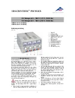
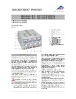
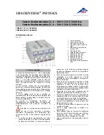
The 0 – 500 V DC power supply provides four inde-
pendently adjustable DC voltages, and is especially 
intended for operating electron tubes, including 
Helmholtz coils. 

The DC voltages are stabilised and regulated, floating 
and galvanically isolated from one another, short 
circuit proof and secure from external voltages The 
output voltages are shown by four analogue displays. 

The DC power supply 1003307 is for operation with a 
mains voltage of 115 V (±10%), and the unit 1003308 
is for operation with a mains voltage of 230 V 
(±10%). 


3. Technical data  

500 V output: 

Voltage: 

0 - 500 V DC, max. 50 mA 

Stability at full load: 


0.01 % ± 100 mV 

Residual ripple: 


20 mV 

50 V output: 

Voltage: 

0 - 50 V DC, max. 50 mA 

Stability at full load: 


0.1 % ± 30 mV 

Residual ripple: 


5 mV 

8 V output: 

Voltage: 

0 - 8 V DC, max. 3 A 

Stability at full load: 


0.1 % ± 30 mV 

12 V output: 

Voltage: 

0 - 12 V DC, max. 4 A 

Stability at full load: 


0.1 % ± 30 mV 

Mains voltage: 

see rear of housing 

Primary fuse: 

see rear of housing 

Displays: 

analogue, class 2 

Terminals: 

4 mm safety sockets 

Power consumption: 

50 VA 

Dimensions: 85x325x190 

mm

 approx. 

Weight: 

4 kg approx. 


4. Operation  

4.1 General information 


Before switching on the DC power supply, set all four 
voltage regulators to zero (turn fully to the left). 


Connect the power supply to the experimental setup. 


Do not switch the power supply on until the 
experiment has been fully assembled. 


Changes to the experimental setup must only be 
made with the power supply switched off. 


Set the required voltages. 


Before switching off the DC power supply, set the 
voltage regulators to zero again (turn fully to the left). 


4.2  Changing the fuse 


Turn off the power switch and unplug the mains plug. 


Unscrew the fuse holder on the rear side of the 
housing with a screwdriver. 


Replace the fuse and reinsert the holder in its socket. 


5. Care and maintenance 


Before cleaning the equipment, disconnect it 
from its power supply. 


Use a soft, damp cloth to clean it. 


6. Disposal 


The packaging should be disposed of at local 
recycling points. 


Should you need to dispose of the equipment 
itself, never throw it away in normal domestic 
waste. Local regulations for the disposal of elec-
trical equipment will apply. 


7. Examples of use 

The 0 – 500 V DC power supply is especially suitable 
for use as a voltage source with the following tubes: 

1. Fine beam tube 


             1000904 

2. Training oscilloscope 


             1000902 

3. Dual pole tube  


             1008521 

4. Electron tubes in the S and D tube ranges 


Summary of Contents for 1003308

Page 1: ...ch den ist das Ger t unverz glich au er Betrieb zu setzen In Schulen und Ausbildungseinrichtungen ist der Betrieb des Ger tes durch geschultes Personal ver antwortlich zu berwachen Achtung Die Nieders...

Page 2: ...sbuchsen Leistungsaufnahme 50 VA Abmessungen ca 85x325x190 mm3 Masse ca 4 kg 4 Bedienung 4 1 Allgemeine Hinweise Vor dem Einschalten des Netzger ts alle Span nungssteller auf 0 stellen linker Anschlag...

Page 3: ...er Diode S 1000613 Abh ngigkeit des Anodenstroms IA von der Heizspannung UF und Nachweis des Anodenstroms IA mit einem Messger t DC POWER SUPPLY 0 500 V 0 500 V 0 50 V V V V V 0 1 0 0 2 0 03 0 0 4 0 0...

Page 4: ...0 5 0 0 2 4 6 8 0 3 6 9 1 2 A Z A DC POWER SUPPLY 0 5 kV KV 0 1 2 3 4 5 0 5 KV Z Fig 3 Beispielhafte Beschaltung der Thomson R hre S 1000617 Bestimmung der spezifischen Ladung des Elektrons e m mitte...

Page 5: ...age the equipment should be switched off immediately and secured against any unintended use In schools and other educational institutions the operation of the power supply unit must be super vised by...

Page 6: ...bility at full load 0 1 30 mV Mains voltage see rear of housing Primary fuse see rear of housing Displays analogue class 2 Terminals 4 mm safety sockets Power consumption 50 VA Dimensions 85x325x190 m...

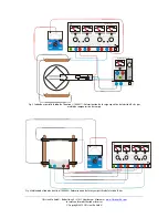
Page 7: ...0 2 0 3 0 4 0 5 0 0 2 4 6 8 0 3 6 9 1 2 UA UF Fig 1 Example of a circuit for the diode S 1000613 Determining dependency of anode current IA on filament voltage UF and confirmation of anode current IA...

Page 8: ...4 6 8 0 3 6 9 1 2 A Z A DC POWER SUPPLY 0 5 kV KV 0 1 2 3 4 5 0 5 KV Z Fig 3 Example of a circuit for the Thomson tube S 1000617 Determination of the specific charge e m of an electron using the fiel...

Page 9: ...lisation de l appareil dans les coles et centres de formation doit tre contr l e par du personnel qualifi sous la responsabilit de ce dernier Attention Les sorties basse tension de l alimentation ne r...

Page 10: ...sance absorb e 50 VA Dimensions env 85x325x190 mm3 Masse env 4 kg 4 Manipulation 4 1 Remarques g n rales Positionner tous les boutons de r glage de tension sur 0 avant de brancher l alimentation but e...

Page 11: ...elation entre le courant anodique IA et la tension de chauffage UF et d monstration du courant anodique IA l aide d un instrument de mesure DC POWER SUPPLY 0 500 V 0 500 V 0 50 V V V V V 0 1 0 0 2 0 0...

Page 12: ...4 0 5 0 0 2 4 6 8 0 3 6 9 1 2 A Z A DC POWER SUPPLY 0 5 kV KV 0 1 2 3 4 5 0 5 KV Z Fig 3 Connexion exemplaire du tube de Thomson S 1000617 D termination de la charge sp cifique de l lectron e m par c...

Page 13: ...recchio Attenzione Le uscite di bassa tensione dell alimentatore non sono resistenti alla tensione in caso di applicazione esterna di tensioni superiori a 500 V contro il potenziale di terra In caso d...

Page 14: ...eso ca 4 kg 4 Comandi 4 1 Indicazioni generali Prima di accendere l alimentatore impostare tutti i regolatori di tensione su 0 battuta sinistra Collegare la struttura sperimentale all alimentatore Acc...

Page 15: ...00613 Rapporto di dipendenza della corrente anodica IA dalla tensione di accensione UF e misurazione della corrente anodica IA DC POWER SUPPLY 0 500 V 0 500 V 0 50 V V V V V 0 1 0 0 2 0 03 0 0 4 0 0 5...

Page 16: ...6 8 0 3 6 9 1 2 A Z A DC POWER SUPPLY 0 5 kV KV 0 1 2 3 4 5 0 5 KV Z Fig 3 Cablaggio di esempio del tubo di Thomon S 1000617 Determinazione della carica specifica dell elettrone e m mediante compensa...

Page 17: ...blemente por personal instruido al respecto Atenci n Las salidas de baja tensi n de la fuente de red no son resistentes a tensiones conectadas externamente con potenciales por encima de los 500 V con...

Page 18: ...ntes de conectar la fuente de tensi n se ponen en 0 todos los ajustes de las tensiones extremo izquierdo Se interconecta el montaje experimental con la fuente de alimentaci n Se conecta la fuente de a...

Page 19: ...613 Dependencia de la corriente an dica IA de la tensi n de caldeo UF y demostraci n de la corriente an dica IA con un aparato de medici n DC POWER SUPPLY 0 500 V 0 500 V 0 50 V V V V V 0 1 0 0 2 0 03...

Page 20: ...5 0 0 2 4 6 8 0 3 6 9 1 2 A Z A DC POWER SUPPLY 0 5 kV KV 0 1 2 3 4 5 0 5 KV Z Fig 3 Cableado especial del tubo de Thomson S 1000617 Determinaci n de la carga espec fica del electr n B e m por medio...

Page 21: ...ho deve ocorrer sob a responsabilidade de pessoas preparadas para a opera o do aparelho Aten o As sa das de baixa tens o da fonte de alimenta o n o tem estabilidade tensional em caso de aplica es de t...

Page 22: ...tiliza o 4 1 Indica es gerais Antes de ligar o aparelho levar todos os bot es de ajuste de tens o ao zero bloqueio esquerda Conectar a montagem experimental com o aparelho fonte de alimenta o S ligar...

Page 23: ...13 Depend ncia da corrente an dica IA da tens o de aquecimento UF e com prova o da corrente an dica IA com um aparelho de medi o DC POWER SUPPLY 0 500 V 0 500 V 0 50 V V V V V 0 1 0 0 2 0 03 0 0 4 0 0...

Page 24: ...0 4 0 5 0 0 2 4 6 8 0 3 6 9 1 2 A Z A DC POWER SUPPLY 0 5 kV KV 0 1 2 3 4 5 0 5 KV Z Fig 3 Conex o exemplar do tubo de Thomson S 1000617 Determina o da carga espec fica do e m por meio da compensa o d...

Reviews: