


3
4. Anwendungsbeispiele
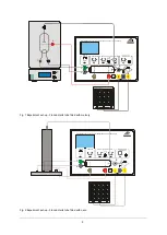
4.1 Franck-Hertz-Röhre mit Hg-Füllung
Zusätzlich erforderlich:
1 Franck-Hertz-Röhre mit Hg-Füllung und Heiz-
ofen (230 V, 50/60 Hz)
1006795
oder
1 Franck-Hertz-Röhre mit Hg-Füllung und Heiz-
ofen (115 V, 50/60 Hz)
1006794
1 Analog-Oszilloskop, 2x 30 MHz
1002727
1 HF-Kabel, 1 m
1002746
2 HF-Kabel, BNC / 4-mm-Stecker
1002748
Sicherheitsexperimentierkabel
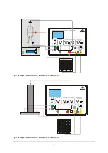
Frontplatte an die offene Heizofenseite set-
zen und mit den 6 Rändelschrauben befesti-
gen.
Heizofen und Betriebsgerät zunächst ausge-
schaltet lassen und alle Stellknöpfe des Be-
triebsgeräts zum linken Anschlag drehen.
Spannung nicht an die kalte Röhre anlegen
(Kurzschlussgefahr durch das enthaltene
Quecksilber).
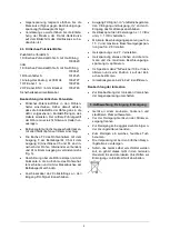
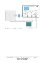
Die Ein-
bzw. Ausgänge „A“, „F“ und „K“ mit-
einander verbinden (siehe Fig. 1).
Ausgang „E“ der Franck-Hertz-Röhre mittels
BNC-Kabel mit dem entsprechenden Ein-
gang des Betriebsgerätes verbinden.
Ausgang FH Signal „
U
Y
“ am Betriebsgerät an
den Y-
Eingang und Ausgang „
U
X
“ an den X-
Eingang des Oszillskops anschließen.
Heizofen einschalten, Temperatur von ca.
210° C einstellen und abwarten bis die Röhre
aufgeheizt ist (ca. 5 bis 10 min.).
Betriebsgerät einschalten, das Gerät befindet
sich im Rampenmodus.
Heizspannung 6 V − 7 V einstellen. Die indi-
rekt geheizte Kathode benötigt nach Anlegen
der Heizspannung eine Anheizzeit von ca.
1:30 min.
Minimale Beschleunigungsspannung auf Null
stellen, maximale Beschleunigungsspannung
langsam auf 80 V erhöhen.
Die Beschleunigungsspannung jedoch nur so
weit erhöhen, dass in der Röhre keine selb-
ständige Entladung auftritt, denn durch
Stoßionisation wird die Kurve gestört.
Oszilloskop zunächst mit den Einstellungen
x = 1 V/Div und y = 1 V/Div betreiben.
Die Entstehung der Maxima der Franck-Hertz-
Kurve auf dem Bildschirm des Oszilloskops be-
obachten.
Parameter Beschleunigungsspannung, Ka-
thodenheizung,
Gegenspannung
und
Amplitude so einstellen, dass eine Kurve mit
gut ausgeprägten Maxima/Minima entsteht.
Das beschriebene Verfahren ist eine allgemeine
Einstellprozedur. Da die Franck-Hertz-Röhren in
Handarbeit gefertigt werden, gibt es zwischen den
verschiedenen Röhren sehr große Unterschiede
der optimalen Parameter. Einen Anhaltspunkt für
gute Werte liefert das den Röhren beiliegende
Messprotokoll.
Der Auffängerstrom weist in Abhängigkeit von
der Beschleunigungsspannung periodisch wie-
derkehrende und äquidistante Maxima und Mi-
nima auf. Der Abstand zwischen den Maxima be-
trägt 4,9 V. In der Röhre besteht zwischen Ka-
thode und Anode ein Kontaktpotenzial von 2 V.
Dies ist die Ursache warum das erste Maximum
bei etwa 7 V liegt. Die ersten Maxima sind besser
ausgeprägt, wenn die Ofentemperatur niedriger
ist.
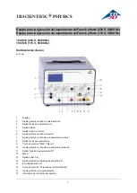
4.2 Franck-Hertz-Röhre mit Ne-Füllung
Zusätzlich erforderlich:
1 Franck-Hertz-Röhre mit Ne-Füllung auf An-
schlusssockel
1000912
1 Analog-Oszilloskop, 2x 30 MHz
1002727
1 HF-Kabel, 1 m
1002746
2 HF-Kabel, BNC / 4-mm-Stecker
1002748
Sicherheitsexperimentierkabel
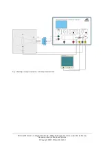
Betriebsgerät zunächst ausgeschaltet las-
sen, mit allen Stellknöpfen auf linkem An-
schlag.
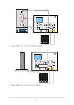
Beschaltung gemäß Fig. 2 vornehmen.
Betriebsgerät einschalten, das Gerät befin-
det sich im Rampenmodus.
Oszilloskop im XY-Modus mit den Einstellun-
gen x = 1 V/Div und y = 2 V/Div betreiben.
Heizspannung langsam erhöhen bis der
Heizfaden anfängt schwach rötlich zu glü-
hen. Dann ca. 30 Sekunden warten bis die
Betriebstemperatur erreicht ist.
Minimale Beschleunigungsspannung auf Null
stellen, maximale Beschleunigungsspannung
von 80 V und Steuergitterspannung von 9 V
wählen.
Die optimale Heizspannung liegt zwischen 4 und
12 V. Sie ist fertigungsbedingt von Röhre zu
Röhre unterschiedlich.
Heizspannung langsam weiter erhöhen bis
ein orangefarbenes Leuchten zwischen der
Kathode und Steuergitter sichtbar wird. Jetzt
die Heizspannung langsam so weit zurück
drehen bis das Leuchten verschwindet und
nur noch der Heizfaden glüht.


