


2
1. Safety instructions
The apparatus conforms to the safety require-
ments for electrical equipment for measurement,
control and laboratory use of DIN EN 61010 part 1
and is classified as belonging to protection class I.
It is intended for operation in dry rooms that are
suitable for electrical equipment or installations.
Safe operation of the apparatus is guaranteed with
correct handling. However, safety is not guaran-
teed if the apparatus is handled improperly or
carelessly. If it is to be expected that safe opera-
tion is impossible (e.g., in case of visible damage),
the apparatus is to be rendered inoperative imme-
diately and to be safeguarded from unintentional
use.
In schools and training institutions, operation of the
apparatus is to be responsibly supervised by trained
personnel.
Before first use, check if the apparatus is de-
signed for local line voltage.
Before start of the experiment, check the ap-
paratus for damage.
In case of visible damage or functional anom-
alies, render the apparatus inoperative imme-
diately.
The instrument may only be connected to the
mains via a socket that has an earth connec-
tion.
Allow only trained electronics specialists to
open the apparatus.
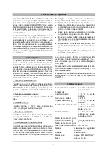
2. Description
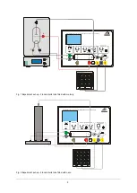
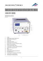
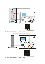
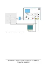
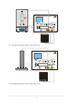
The Franck-Hertz control unit can be used to op-
erate the mercury filled Franck-Hertz tube, the
neon filled Franck-Hertz tube or the critical poten-
tial tubes S. It provides all the voltages needed to
power the tubes and includes a highly sensitive
built-in DC amplifier for measuring collector cur-
rent.
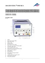
1. Accelerating voltage
U
A
:
Choice of 0
− 80 V stabilised DC voltage
("Man(ual)" mode) or 50 Hz saw-tooth voltage
("Ramp mode"). At the oscilloscope output
U
X
this
voltage is divided by 10.
2. Heater voltage
U
F
:
DC voltage 0
− 12 V for the heater filament of the tube.
3. Countervoltage
U
E
:
DC voltage of 0
− 12 V for reverse bias between
grid and collector electrode.
4. Control voltage
U
G
:
DC voltage of 0
− 12 V between the control grid
and the cathode in the neon-filled Franck-Hertz
tube
5. DC amplifier:
The DC amplifier provides a voltage proportional
to the collector current, rated up to 10 mA. At the
lowest amplification 1 V of voltage measured cor-
responds to an electron current of 38 nA approx.
and at the highest amplification to an electron cur-
rent of 12 nA approx.
The voltages can simultaneously be read off a dis-
play.
Additional measuring inputs are also available for
the anode current and accelerating voltage.
The apparatus 1012818 is for operation with a
mains voltage of 115 V (±10%), and the unit
1012819 is for operation with a mains voltage of
230 V (±10%).
3. Technical data
Mains voltage:
See back of chassis
Filament voltage
U
F
:
0
− 12 V, continuously
adjustable
Heater current:
0
− 2.5 A
Control voltage
U
G
:
0
− 12 V, continuously
adjustable
Accelerating voltage
U
A
: 0
− 80 V, continuously
adjustable or saw-tooth
Countervoltage
U
E
:
0
− ±12 V, continuously
adjustable, switchable
polarity
Output
U
Y
for
collector current
I
E
:
I
E
=
U
A
*38 nA/V (0
−12V)
Output
U
X
for
accelerating voltage
U
A
:
U
X
= U
A
/ 10
Outputs:
4 mm safety sockets
Input:
BNC socket
Dimensions:
160x132x210 mm
3
approx.
Weight:
3.4 kg approx.


