background image

4. Examples of use 

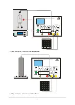
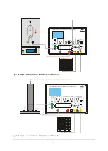
4.1  Franck-Hertz tube with Hg filling 

Additionally required: 

1 F/H tube w. Hg filling a. heating chamber (230 V, 
50/60 Hz) 

1006795 

or 

1 F/H tube w. Hg filling a. heating chamber (115 V, 
50/60 Hz) 

1006794 

1 Analogue oscilloscope, 2x 30 MHz  1002727 

1 HF patch cord, 1 m 

1002746 

2 HF patch cords, BNC / 4-mm plug  1002748 

Safety leads for experiments 


Place front plate of the open side of the heat-
ing chamber and fix it in place with 6 knurled 
screws. 


Turn off the heating chamber and the control 
unit to begin with and turn all the knobs on the 
control fully to the left. 


Do not apply a voltage to the tube when it is 
still  cold  (the  mercury  inside  may  cause  a 
short circuit). 


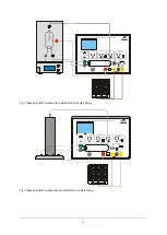
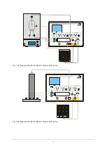
Connect  terminals  "A",  "F"  and  "K"  (refer  to 
Fig. 1).  


Connect terminal "E" of the Franck-Hertz tube 
to  the  correct  input  on  the  control  unit  by 
means of an BNC cable.  


Connect  the  “FH  Signal  UY-out”  terminal  of 
the  control  unit  to  the  Y  input  of  the  oscillo-
scope and terminal “UX” to the X input. 


Turn on the heating chamber. Set a tempera-
ture of about 210° C and wait for the tube to 
warm up (about 5 to 10 minutes). 


Turn  on  the  control  unit  and  the  equipment 
should enter ramp mode. 


Set a filament voltage of 6 

− 7 V. The indirectly 

heated cathode requires about 90 seconds to 
warm up, once the voltage is applied. 


Set the minimum acceleration voltage to zero, 
slowly  increase  the  maximum  acceleration 
voltage to 80 V. 


Do  not,  however,  increase  the  accelerating 
voltage so much that self-discharge no longer 
occurs inside the  tube. Any  ionisation due to 
collisions will disrupt the curve. 


Set up the oscilloscope initially with settings of 
x = 1 V/div and y = 1 V/div. 


Observe the emergence of the maxima in the 
Franck-Hertz  trace  on  the  oscilloscope 
screen. 


Set  up  all  the  parameters,  accelerating  volt-
age, cathode filament, bias voltage and ampli-
tude  so  that  a  trace  with  nicely  delineated 
maxima and minima is obtained. 

The  procedure  as  described  so  far  is  a  general 
setting  procedure.  Since  the  Franck-Hertz  tubes 
are  hand-made,  there  may  be  quite  large  differ-
ences  in  the  optimum  parameters from  one  tube 
to the next. The test report included with the tube 
should give some idea of where good results may 
be obtained for the tube in question. 

The  collector  current  displays  regularly  recurring, 
equidistant maxima and minima that are independ-
ent  of  the  accelerating  voltage.  The  interval  be-
tween these peaks is 4.9 V. A contact potential of 
2 V exists between  the anode  and cathode of the 
tube, which is why the first maximum only appears 
in the region of 7 V. The first maxima will be more 
obvious  when  the  temperature  of  the  heating 
chamber is lower. 

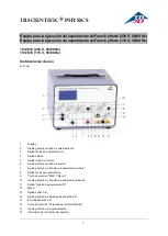
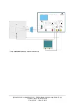
4.2  Franck-Hertz tube with Ne filling 

Additionally required: 

1 Franck-Hertz tube with Ne filling 

1000912 

1 Analogue oscilloscope, 2x 30 MHz 

1002727 

1 HF lead, 1 m 

1002746 

2 HF leads, BNC / 4-mm plug 

1002748 

Safety leads for experiments 


Start with the voltage supply unit switched off, 
and  with all the  voltage setting knobs fully to 
the left. 


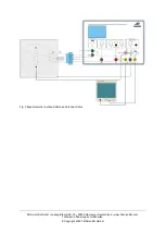
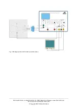
Connect  up  the  experiment  as  shown  in  Fig. 
2. 


Turn  on  the  equipment.  It  will  start  in  ramp 
mode. 


Set  up  the  oscilloscope  in  XY  mode  with 
x = 1 V/div and y = 2 V/div. 


Gradually  increase  the  heater  voltage  till  the 
filament starts to faintly glow red. Then wait 30 
seconds  till  it  reaches  its  operating  tempera-
ture. 


Set the minimum acceleration voltage to zero, 
choose a maximum acceleration voltage of 80 
V and set the control grid voltage to 9 V.  

The  ideal  filament  voltage  should  be  between  4 
and  12 V.  This  differs  from  tube  to  tube  due  to 
manufacturing tolerances. 


Gradually  increase  the  filament  voltage  until 
an orange glow appears between the cathode 
and the grid. Then turn down the filament volt-
age till the glow disappears and only the fila-
ment is glowing. 

Summary of Contents for 1012818

Page 1: ...annung 4 Ausgang Kathode 5 Ausgang Steuergitter 6 Drehsteller Steuerspannung 7 Drehsteller minimale Beschleunigungsspannung 8 Ausgang Beschleunigungsspannung 9 Wahltaster Man Ramp 10 Drehsteller maximale Beschleunigungsspannung 11 Ausgang Beschleunigungsspannung 10 12 Massebuchse 13 Ausgang F H Signal 14 Drehsteller Amplitude F H Signal 15 Eingang F H Signal 16 Wahltaster Polarität der Gegenspannu...

Page 2: ...der Röhren und hat einen einge bauten hochempfindlichen Gleichstromverstärker zur Messung des Auffängerstroms 1 Beschleunigungsspannung UA Wahlweise 0 80 V stabilisierte Gleichspannung Modus Man oder Sägenzahnspannung 50 Hz Modus Ramp Am Oszilloskopausgang UX ist diese Spannung durch 10 geteilt 2 Heizspannung UF Gleichspannung 0 12 V für den Heizfaden der Röhre 3 Gegenspannung UE Gleichspannung 0 ...

Page 3: ...nheizung Gegenspannung und Amplitude so einstellen dass eine Kurve mit gut ausgeprägten Maxima Minima entsteht Das beschriebene Verfahren ist eine allgemeine Einstellprozedur Da die Franck Hertz Röhren in Handarbeit gefertigt werden gibt es zwischen den verschiedenen Röhren sehr große Unterschiede der optimalen Parameter Einen Anhaltspunkt für gute Werte liefert das den Röhren beiliegende Messprot...

Page 4: ...stülpen mit der Falzkante in die Aufnahme des Röhrenhal ters schieben und mit der Massebuchse am Betriebsgerät verbinden Anschlusskabel des Kollektorrings an den Eingang F H Signal E anschließen Ausgang FH Signal UY am Betriebsgerät an den Y Eingang und Ausgang UX an den X Eingang des Oszillskops anschließen Oszilloskop mit den Einstellungen x 1 V Div und y 1 V Div betreiben Minimale Beschleunigun...

Page 5: ...eschleunigung Acceleration Reverse bias E V Man Ramp 1 10 U U x A 1 10 U I V Y E UF V UG V UAmin V UAmax V 0 0 0 80 80 12 UE V 0 12 EXT CH1 X CH2 Y OSCILLOSCOPE E F K A BETRIEBSGERÄT FRANCK HERTZ OPERATING UNIT FRANCK HERTZ F K G A Heizung Filament Gitter Grid Beschleunigung Acceleration Reverse bias E V Man Ramp 1 10 U U x A 1 10 U I V Y E UF V UG V UAmin V UAmax V 0 0 0 80 80 12 UE V 0 12 EXT CH...

Page 6: ...cientific GmbH Ludwig Erhard Str 20 20459 Hamburg Deutschland www 3bscientific com Technische Änderungen vorbehalten Copyright 2022 3B Scientific GmbH Fig 3 Experimenteller Aufbau Kritisches Potenzial Röhre ...

Page 7: ...ltage output 4 Cathode output 5 Control grid output 6 Rotary knob for control voltage 7 Rotary knob for minimum accelerating voltage 8 Accelerating voltage output 9 Man ual Ramp selector switch 10 Rotary knob for maximum accelerating voltage 11 Output accelerating voltage 10 12 Ground socket 13 F H signal output 14 Rotary knob for F H signal amplitude 15 F H signal input 16 Polarity of reverse bia...

Page 8: ...highly sensitive built in DC amplifier for measuring collector cur rent 1 Accelerating voltage UA Choice of 0 80 V stabilised DC voltage Man ual mode or 50 Hz saw tooth voltage Ramp mode At the oscilloscope output UX this voltage is divided by 10 2 Heater voltage UF DC voltage 0 12 V for the heater filament of the tube 3 Countervoltage UE DC voltage of 0 12 V for reverse bias between grid and coll...

Page 9: ...olt age cathode filament bias voltage and ampli tude so that a trace with nicely delineated maxima and minima is obtained The procedure as described so far is a general setting procedure Since the Franck Hertz tubes are hand made there may be quite large differ ences in the optimum parameters from one tube to the next The test report included with the tube should give some idea of where good resul...

Page 10: ...e push its folded edge into the opening in the tube holder and connect it to the earth socket on the con trol unit Connect the lead from the collector ring to the F H signal input socket E Connect the FH Signal UY out terminal of the control unit to the Y input of the oscilloscope and terminal UX to the X input Set up the oscilloscope initially with settings of x 1 V div and y 1 V div Set the mini...

Page 11: ...chleunigung Acceleration Reverse bias E V Man Ramp 1 10 U U x A 1 10 U I V Y E UF V UG V UAmin V UAmax V 0 0 0 80 80 12 UE V 0 12 EXT CH1 X CH2 Y OSCILLOSCOPE E F K A BETRIEBSGERÄT FRANCK HERTZ OPERATING UNIT FRANCK HERTZ F K G A Heizung Filament Gitter Grid Beschleunigung Acceleration Reverse bias E V Man Ramp 1 10 U U x A 1 10 U I V Y E UF V UG V UAmin V UAmax V 0 0 0 80 80 12 UE V 0 12 EXT CH1 ...

Page 12: ...3B Scientific GmbH Ludwig Erhard Str 20 20459 Hamburg Germany www 3bscientific com Subject to technical amendments Copyright 2022 3B Scientific GmbH Fig 3 Experiment set up critical potential tube ...

Page 13: ...alentamiento 4 Salida cátodo 5 Salida rejilla de control 6 Ajuste giratorio tensión de control 7 Ajuste giratorio de tensión de aceleración mínima 8 Salida tensión de aceleración 9 Tecla de elección Man Ramp 10 Ajuste giratorio de tensión de aceleración máxima 11 Salida tensión de aceleración 10 12 Masa 13 Salida señal F H 14 Ajuste giratorio de amplitud de señal de F H 15 Entrada señal de F H 16 ...

Page 14: ...to de los tubos y posee un amplificador de co rriente continua incorporado sensible para la me dición de la corriente de colector 1 Tensión de aceleración UA Tensión cotinua de 0 a 80 V estabilizada Modo Man resp tensión de dientes de sierra 50 Hz Modo Ramp En la salida para osciloscopio UX se tiene a disposición esta tensión dividida por 10 2 Tensión de calentamiento UF Tensión continua 0 12 V pa...

Page 15: ... ajustes x 1 V Div resp y 1 V Div Se observa en la pantalla del osciloscopio la apa rición del los máximos de la curva de Franck Hertz Los parámetros Tensión de aceleración ca lefacción del cátodo tensión inversa y ampli tud se ajustan de tal forma que se pueda ob servar en la pantalla del osciloscopio una curva con máximos y mínimos bien definidos El procedimiento descrito es un proceso de ajuste...

Page 16: ...o se conecta con la salida F del aparato de control C5 con la salida K los contactos C5 y F4 están conec tados entre si dentro del tubo y A1 se conecta con la salida A ver fig 3 El apantallamiento se coloca alrededor del tubo y el borde plagado se inserta en la toma del soporte del tubo y se conecta con el cas quillo de masa del aparato de control Se conecta el cable de conexión del anillo co lect...

Page 17: ...hleunigung Acceleration Reverse bias E V Man Ramp 1 10 U U x A 1 10 U I V Y E UF V UG V UAmin V UAmax V 0 0 0 80 80 12 UE V 0 12 EXT CH1 X CH2 Y OSCILLOSCOPE E F K A BETRIEBSGERÄT FRANCK HERTZ OPERATING UNIT FRANCK HERTZ F K G A Heizung Filament Gitter Grid Beschleunigung Acceleration Reverse bias E V Man Ramp 1 10 U U x A 1 10 U I V Y E UF V UG V UAmin V UAmax V 0 0 0 80 80 12 UE V 0 12 EXT CH1 X...

Page 18: ...tific GmbH Ludwig Erhard Str 20 20459 Hamburgo Alemania www 3bscientific com Se reservan las modificaciones técnicas Copyright 2022 3B Scientific GmbH Fig 3 Montaje de experimentación tubo del potencial crítico ...

Page 19: ... Sortie cathode 5 Sortie grille de commande 6 Bouton tournant tension de commande 7 Bouton tournant tension d accélération minimale 8 Sortie tension d accélération 9 Bouton sélecteur Man Rampe 10 Bouton tournant tension d accélération minimale 11 Sortie tension d accélération 10 12 Douille de masse 13 Sortie signal F H 14 Bouton tournant am plitude du signal F H 15 Entrée signal F H 16 Bouton séle...

Page 20: ...ssède un amplificateur de courant continu très sensible intégré permettant de mesurer le courant de captage 1 Tension d accélération UA Au choix tension continue stabilisée 0 80 V Mode Man ou tension en dents de scie 50 Hz Mode Rampe À la sortie de l oscilloscope UX cette tension est divisée par dix 2 Tension de chauffage UF tension continue 0 12 V pour le filament du tube 3 Contre tension UE tens...

Page 21: ... paramètres de tension d accéléra tion de chauffage de cathode de contre ten sion et d amplitude de manière à former une courbe aux maxima et minima prononcés La méthode décrite est une procédure de ré glage générale Comme les tubes de Franck et Hertz sont confectionnés à la main les pa ramètres optimaux varient fortement d un tube à l autre Le rapport de mesures joint aux tubes fournit une référe...

Page 22: ...sont connectés ensemble à l intérieur du tube et A1 à la sortie A voir fig 3 Coiffez le tube de sa protection poussez cette dernière avec son bord replié dans le lo gement du support pour tube puis raccordez le tout à la prise de terre commune sur l ap pareil d exploitation Raccordez le cordon de raccordement du col lecteur à l entrée signal F H Reliez la sortie UY de l appareil de service à l ent...

Page 23: ...leunigung Acceleration Reverse bias E V Man Ramp 1 10 U U x A 1 10 U I V Y E UF V UG V UAmin V UAmax V 0 0 0 80 80 12 UE V 0 12 EXT CH1 X CH2 Y OSCILLOSCOPE E F K A BETRIEBSGERÄT FRANCK HERTZ OPERATING UNIT FRANCK HERTZ F K G A Heizung Filament Gitter Grid Beschleunigung Acceleration Reverse bias E V Man Ramp 1 10 U U x A 1 10 U I V Y E UF V UG V UAmin V UAmax V 0 0 0 80 80 12 UE V 0 12 EXT CH1 X ...

Page 24: ...ntific GmbH Ludwig Erhard Str 20 20459 Hamburg Allemagne www 3bscientific com Sous réserve de modifications techniques Copyright 2022 3B Scientific GmbH Fig 3 Montage expérimental du tube à potentiel critique ...

Page 25: ...ita reticolo di controllo 6 Selettore rotativo tensione di controllo 7 Selettore rotativo tensione di accelerazione minima 8 Uscita tensione di accelerazione 9 Selettore Man Ramp 10 Selettore rotativo tensione di accelerazione massima 11 Uscita tensione di accelerazione 10 12 Presa di massa 13 Uscita segnale F H 14 Selettore rotativo ampiezza del segnale F H 15 Ingresso segnale F H 16 Selettore Po...

Page 26: ... continua a elevata sensibilità e incorporato per la misurazione della corrente bersaglio 1 Tensione di accelerazione UA tensione continua stabilizzata a scelta 0 80 V modalità Man oppure tensione a dente di sega 50 Hz modalità Ramp all uscita dell oscilloscopio UX questa tensione viene divisa per 10 2 Tensione di riscaldamento UF tensione continua 0 12 V per il filamento caldo del tubo 3 Forza co...

Page 27: ...con le impostazioni x 1 V Div e y 1 V Div Osservare la formazione dei valori massimi della curva di Franck Hertz sullo schermo dell oscilloscopio Impostare i parametri di tensione di accelerazione riscaldamento catodo forza controelettromotrice e ampiezza in modo che si formi una curva con valori massimi e minimi marcati La procedura descritta è una procedura di impostazione generale Poiché il tub...

Page 28: ... con tutte le manopole di regolazione sulla battuta sinistra Collegare il jack F3 del portatubo con l uscita F sull apparecchio C5 con l uscita K le connessioni C5 e F4 sono unite fra loro all interno del tubo e A1 con l uscita A vedere fig 3 Collocare la schermatura sul tubo spingerla con il bordo scanalato nell alloggiamento del portatubo e collegarla alla presa di terra presso l apparecchio Col...

Page 29: ...rid Beschleunigung Acceleration Reverse bias E V Man Ramp 1 10 U U x A 1 10 U I V Y E UF V UG V UAmin V UAmax V 0 0 0 80 80 12 UE V 0 12 EXT CH1 X CH2 Y OSCILLOSCOPE E F K A A A H H K K M BETRIEBSGERÄT FRANCK HERTZ OPERATING UNIT FRANCK HERTZ F K G A Heizung Filament Gitter Grid Beschleunigung Acceleration Reverse bias E V Man Ramp 1 10 U U x A 1 10 U I V Y E UF V UG V UAmin V UAmax V 0 0 0 80 80 ...

Page 30: ...Scientific GmbH Ludwig Erhard Str 20 20459 Amburgo Germania www 3bscientific com Con riserva di modifiche technici Copyright 2022 3B Scientific GmbH Fig 3 Struttura sperimentale tubo per potenziale critico ...

Page 31: ...ento 4 Saída cátodo 5 Saída grade de controle 6 Botão rotativo tensão de controle 7 Botão rotativo da tensão de aceleração mínima 8 Saída tensão de aceleração 9 Botão de seleção Man Ramp 10 Botão rotativo da tensão de aceleração máxima 11 Saída tensão de aceleração 10 12 Conector massa 13 Saída sinal F H 14 Botão rotativo da amplitude do sinal F H 15 Entrada sinal F H 16 Botão de seleção Polaridad...

Page 32: ...a a operação do tubo e tem um amplificador altamente sensível de corrente contínua integrado para a medição da corrente do captador 1 Tensão de aceleração UA Forma de seleção 0 80 V tensão contínua estabilizada Modo Man ou tensão dente de serra de 50 Hz Modo Ramp Na saída do osciloscópio UX esta tensão é dividida por 10 2 Tensão de aquecimento UF Tensão contínua 0 12 V para o filamento de aquecime...

Page 33: ...ea já que a ionização repentina destruiria a curva Por enquanto operar o osciloscópio com as regulagens x 1 V Div e y 1 V Div Observar o surgimento da máxima da curva de Franck Hertz na tela do osciloscópio Ajustar os parâmetros tensão de aceleração aquecedor do cátodo contra tensão e amplitude de modo que surja uma curva com máximas e mínimas bem definidas O método descrito é um procedimento gera...

Page 34: ...operacional desligado com todos os botões virados totalmente para a esquerda Ligar a tomada F3 do suporte de tubo com a saída F no aparelho de operação C5 com a saída K Os contatos C5 e F4 estão ligados entre si dentro do tubo e A1 com a saída A vide fig 3 Cobrir o tubo com o protetor inserir a borda do escorregador no receptáculo do suporte de tubo e ligar com a tomada de massa no aparelho de ope...

Page 35: ...ter Grid Beschleunigung Acceleration Reverse bias E V Man Ramp 1 10 U U x A 1 10 U I V Y E UF V UG V UAmin V UAmax V 0 0 0 80 80 12 UE V 0 12 EXT CH1 X CH2 Y OSCILLOSCOPE E F K A BETRIEBSGERÄT FRANCK HERTZ OPERATING UNIT FRANCK HERTZ F K G A Heizung Filament Gitter Grid Beschleunigung Acceleration Reverse bias E V Man Ramp 1 10 U U x A 1 10 U I V Y E UF V UG V UAmin V UAmax V 0 0 0 80 80 12 UE V 0...

Page 36: ... Fig 3 Montagem experimental do tubo de potencial crítico ...

Reviews: