background image

Heating chamber 

Mains voltage 

See back of case 

Dimensions of front  
opening: 

230 x 160 mm² approx. 

Heating power: 

800 W @230 V 


400 W @115 V 

Maximum temperature: 

300°C @230 V 

250°C @115 V 

Temperature constancy: 

±1°C approx. 

Dimensions: 

335x180x165 mm³ approx. 

Weight: 

5.6 kg approx. 

4. Operation 

The  following  equipment  is  also  required  to 
complete the experiment: 

1 Power supply unit for F/H experiment  

@230 V  1012819 

or 

@115 V  1012818 

1 Digital oscilloscope, 2x 30 MHz 

1020910 

1 HF Patch cord, 1 m 

1002746 

2 HF Patch cords, BNC/4 mm plug 

1002748 

Safety leads for experiments 

1002843 


Note:  Before  switching  on,  remove  the 
PE packaging part, which is located be-
hind the tube, from the inside of the heat-
ing oven. 


Place  front  plate  of  the  open  side  of  the 
heating  chamber  and  fix  it  in  place  with  6 
knurled screws. 


Turn off the heating chamber and the con-
trol unit to begin with and turn all the knobs 
on the control fully to the left. 


Do  not  apply  an  accelerating  voltage  to 
the tube when it is still cold (the mercury 
inside may cause a short circuit). 


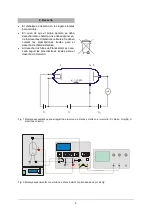
Connect terminals "A", "F" and "K" (refer to fig. 
2).  


Connect  terminal  "E"  of  the  Franck-Hertz 
tube to the correct input on the control unit 
by means of an BNC cable.  


Connect the “FH Signal 

U

Y

-

out” terminal of 

the control unit to the Y input of the oscillo-
scope and terminal “

U

X

” to the X input. 


Turn on the control unit and the equipment 
should enter ramp mode. 


Slowly set a filament voltage of 6 V. The in-
directly  heated  cathode  requires  about  90 
seconds to warm up, once the voltage is ap-
plied. 


Turn on the heating chamber. Set a temper-
ature of about 180° C and wait for the tube 
to warm up (about 5 to 10 minutes). 


Set  the  minimum  acceleration  voltage  to 
zero, slowly increase the maximum acceler-
ation voltage to 80 V. 


Do not, however, increase the accelerating 
voltage  so  much  that  self-discharge  no 
longer occurs inside the tube. Any ionisation 
due to collisions will disrupt the curve. 


Set up the oscilloscope initially with settings 
of x = 1 V/div and y = 1 V/div. 


Observe  the  emergence  of  the  maxima  in 
the  Franck-Hertz  trace  on  the  oscilloscope 
screen. 


Set up all the parameters, accelerating volt-
age, cathode filament, bias voltage and am-
plitude so that a trace with nicely delineated 
maxima and minima is obtained. 

The procedure as described so far is a gen-
eral  setting  procedure.  Unavoidable  differ-
ences resulting from the manufacture of in-
dividual Frank-Hertz tubes mean that the op-
timum  parameters  may  differ  from  tube  to 
tube. The test report included with the tube 
should  give  some  idea  of  where  good  re-
sults may be obtained for the tube in ques-
tion. 

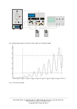
The collector current displays regularly recurring, 
equidistant  maxima  and  minima  that  are  inde-
pendent of the accelerating voltage. The interval 
between these peaks is 4.9 V. A contact potential 
of 2 V exists between the anode and cathode of 
the tube, which is why the first maximum only ap-
pears in the region of 7 V. The first maxima will 
be  more  obvious  when  the  temperature  of  the 
heating chamber is lower. 

Evaluation of the Franck-Hertz curve: 

To fully evaluate the Franck-Hertz curve, a dig-
ital  voltmeter  is  needed. This  does  not  require 
that the current of the electron beam be deter-
mined  precisely.  The  oscilloscope  screen 
should show the trace of a Franck-Hertz curve 
featuring very clear maxima and minima. 


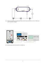
Connect a digital voltmeter between the sig-
nal output (

U

X

) and the ground socket (refer 

to fig. 3). 

Summary of Contents for 1023095

Page 1: ...ist f r den Be trieb in trockenen R umen vorgesehen welche f r elektrische Betriebsmittel oder Einrichtungen geeignet sind Bei bestimmungsgem em Gebrauch ist der si chere Betrieb des Ger tes gew hrle...

Page 2: ...nsymbol Die Franck Hertz R hre ist so montiert dass die ganze R hre einschlie lich der Anschlussdr hte auf eine kon stante Temperatur kommt Dies ist erforderlich weil sich die Dampfdichte des Quecksil...

Page 3: ...80 V erh hen Die Beschleunigungsspannung jedoch nur so weit erh hen dass in der R hre keine selb st ndige Entladung auftritt denn durch Sto ionisation wird die Kurve gest rt Oszilloskop zun chst mit d...

Page 4: ...sich auch die Qualit t der Maxima leicht verbessern Optimierung der Heizspannung Die Heizspannung bestimmt die Anzahl der emit tierten Elektronen und damit den Anodenstrom Je h her die Heizspannung is...

Page 5: ...g 1 Schematischer Aufbau zur Aufzeichnung der Franck Hertz Kurve an Quecksilber C Katode G Gitter A Auff ngerelektrode Fig 2 Experimenteller Aufbau Franck Hertz R hre mit Hg F llung F K G A E X Y E F...

Page 6: ...20 20459 Hamburg Deutschland www 3bscientific com Technische nderungen vorbehalten Copyright 2022 3B Scientific GmbH Fig 3 Experimenteller Aufbau Franck Hertz R hre mit 2 Digital Voltmetern Fig 4 Fran...

Page 7: ...lectrical equipment or installations Safe operation of the equipment is guaranteed provided it is used correctly However there is no guarantee of safety if the equipment is used in an improper or care...

Page 8: ...s and a schematic diagram of the tube The Franck Hertz tube is mounted in such a way that the whole tube and its connecting wires can all be maintained at constant tempera ture This is necessary becau...

Page 9: ...ver increase the accelerating voltage so much that self discharge no longer occurs inside the tube Any ionisation due to collisions will disrupt the curve Set up the oscilloscope initially with settin...

Page 10: ...p or too flat curve with few maxima The countervoltage determines the slope of the curve The greater the countervoltage the flatter the rise In com bination with the acceleration voltage the qual ity...

Page 11: ...5 Fig 1 Schematic of set up for measuring the Franck Hertz curve for mercury C cathode G grid A collector elec trode Fig 2 Experiment set up for Franck Hertz tube with Hg filling F K G A E X Y E F K A...

Page 12: ...tr 20 20459 Hamburg Germany www 3bscientific com Subject to technical amendments Copyright 2022 3B Scientific GmbH Fig 3 Experiment set up for Franck Hertz tube with 2 digital voltmeters Fig 4 Franck...

Page 13: ...clase de protecci n I Est previsto para su uso en recintos secos adecuados para componentes o ins talaciones el ctricas Se garantiza el funcionamiento seguro del aparato mientras se use seg n su obje...

Page 14: ...ones El tubo est montado al dorso de la placa frontal de la estufa de tal forma que se puede intercambiar En la placa frontal se encuen tran casquillos de conexi n de cer mica aislante y adem s el s m...

Page 15: ...UX en la entrada X del osciloscopio Se conecta el aparato de control el aparato se encuentra en modo de rampa Ajuste lentamente la tensi n de caldeo en 6 V El c todo de caldeo indirecto necesita un t...

Page 16: ...aso de la incineraci n de tubos La corriente an dica aumenta r pida mente hasta un valor m ximo En este caso la tensi n de aceleraci n debe reducirse inmediata mente Si fuera necesario trazar m s m xi...

Page 17: ...las prescripciones locales para el desecho de chatarra el ctrica Al desechar los tubos de Franck Hertz es nece sario seguir las prescripciones locales para el desecho de mercurio Fig 1 Montaje esquem...

Page 18: ...amburgo Alemania www 3bscientific com Nos reservamos el derecho a cambios t cnicos Copyright 2022 3B Scientific GmbH Fig 3 Montaje experimental con el tubo de Franck Hertz con 2 volt metros digital Fi...

Page 19: ...asse de protection 1 Il est pr vu pour tre exploit dans des pi ces s ches convenant des quipements ou dispositifs lectriques En cas d utilisation conforme l exploitation s re de l appareil est garanti...

Page 20: ...que et le symbole du tube Le tube de Franck et Hertz est mont de mani re ce que le tube complet et les fils de con nexion atteignent une temp rature constante Ce dispositif est n cessaire car la densi...

Page 21: ...attendez que le tube chauffe 5 10 minutes R glez la tension minimale d acc l ration sur 0 et augmentez lentement la vitesse maximale d acc l ration jusqu 80 V Lorsque vous augmentez la tension d acc...

Page 22: ...nte de la courbe Plus la contre tension est grande plus la mont e est plate En combinaison avec la tension d acc l ration la qualit des maxima peut tre facile ment am lior e Optimisation de la tension...

Page 23: ...ructure sch matique de l enregistrement de la courbe de Franck et Hertz sur le mercure C cathode G grille A lectrode de captage Fig 2 Montage exp rimental du tube de Franck et Hertz au Hg F K G A E X...

Page 24: ...mburg Allemagne www 3bscientific com Sous r serve de modifications techniques Copyright 2022 3B Scientific GmbH Fig 3 Montage exp rimental du tube de Franck et Hertz avec 2 voltm tres num riques Fig 4...

Page 25: ...protezione I L apparecchio pensato per l utilizzo in ambienti asciutti adatti per strumenti o dispositivi elettrici Un utilizzo conforme garantisce il funzionamento sicuro dell apparecchio La sicurezz...

Page 26: ...stituzione Sulla piastra anteriore sono presenti i jack di raccordo isolati in ceramica e il simbolo del tubo Il tubo di Franck Hertz montato in modo che l intero tubo compresi i fili di collegamento...

Page 27: ...di riscaldamento di circa 1 30 min Attivare il forno impostare una temperatura di circa 180 C e attendere fino a quando il tubo non si sar riscaldato circa 5 10 minuti Azzerare la tensione di accelera...

Page 28: ...fosse necessario mappare altri massimi la temperatura del forno deve essere aumentata in anticipo Ottimizzazione della forza controelettromotrice Le figure 5 b e 5 c mostrano una curva troppo ripida o...

Page 29: ...disposizioni vigenti a livello locale Per lo smaltimento del tubo di Frank Hertz ri spettare le disposizioni vigenti a livello locale per lo smaltimento di mercurio Fig 1 Struttura schematica per la...

Page 30: ...hard Str 20 20459 Amburgo Germania Con riserva di modifiche tecniche Copyright 2022 3B Scientific GmbH Fig 3 Struttura sperimentale tubo di Franck Hertz con 2 voltmetri digitali Fig 4 Curva di Franck...

Page 31: ...a a opera o em espa os secos que estejam preparados para aparelhagem ou instala o el trica Se a opera o do aparelho ocorre conforme s instru es de uso a seguran a est ent o garantida A seguran a por m...

Page 32: ...cabos de conex o associados tenham uma temperatura constante Isto necess rio porque a densidade de vaporiza o do merc rio se ajusta conforme o ponto mais frio do tubo As correntes de escapamento sobre...

Page 33: ...ar que o tubo esteja aquecido cerca de 5 a 10 minutos Ajustar a tens o de acelera o m nima em zero elevar lentamente a tens o de acelera o m xima para 80 V Por m s elevar a tens o de acelera o de modo...

Page 34: ...ida Em combina o com a tens o de acelera o a qualidade dos m ximos pode ser facilmente melhorada Otimiza o da tens o do aquecedor A tens o de aquecimento determina o n mero de el trons emitidos e port...

Page 35: ...rutura esquem tica para o registro da curva de Franck Hertz no merc rio C c todo G grade A eletrodo captador Fig 2 Montagem da experi ncia com o tubo de Franck Hertz com preenchimento de Hg F K G A E...

Page 36: ...59 Hamburgo Alemanha www 3bscientific com Sob reserva de altera es t cnicas Copyright 2022 3B Scientific GmbH Fig 3 Montagem da experi ncia com o tubo de Franck Hertz com 2 volt metros digitais Fig 4...

Reviews: