background image


3B SCIENTIFIC® PHYSICS


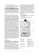
Franck-Hertz Tube with Hg Filling and Heating Chamber 

1023095 (230 V, 50/60 Hz) 
1023094 (115 V, 50/60 Hz)


Instruction sheet 

10/21 ALF/ SD/ GH 


1. Safety instructions 

The apparatus conforms to the safety regulations for 
electrical  test, control  and  laboratory  equipment  as 
specified in DIN EN 61010 Part 1. Its protection clas-
sification is deemed to be class I. It is intended for 
use in dry rooms suitable for electrical equipment or 
installations.  

Safe  operation  of  the  equipment  is  guaranteed, 
provided it is used correctly. However, there is no 
guarantee of safety if the equipment is used in an 
improper or careless manner. If it is deemed that 
the equipment can no longer be operated without 
risk  (e.g.  visible  damage  has  occurred),  the 

equipment  should  be  switched  off  immediately 
and secured against any inadvertent use. 

In schools and training institutions, operation of the 
apparatus is to be responsibly supervised by trained 
personnel. 


Before putting the equipment into operation, con-
firm it is compatible with the local mains voltage. 


Before setting up or starting any experiments, 
check the apparatus for any damage.  


In the event of any malfunction/defect or visi-
ble damage, switch off the equipment imme-
diately and secure it against any inadvertent 
use. 


The instrument may only be connected to the 
mains via a socket that has an earth connec-
tion. 


Only  trained  electricians  are  permitted  to 
open up the apparatus’ housing. 

 
Beware: Risk of burns! The viewing windows and 
the walls of the heating chamber can reach tem-
peratures of up to 300° C during operation. 


Set  up  the  heating  chamber  on  a  heat-re-
sistant surface.  


When the heating chamber is in operation, do 
not attempt to touch or move the apparatus. 
Only move or transport the equipment by us-
ing the insulated handle. 


Allow  the  apparatus  to  cool  before  disman-
tling the experiment. 

 
Beware:  There  is  always  a  risk  that  glass  can 
break and cause injury. 


Use  all  six  knurled  screws  to  affix  the  front 
plate to the heating chamber. 


Do  not  subject  the  tube  to  any  mechanical 
stress.  Do  not  put  kinks  in  any  connecting 
leads.  


Summary of Contents for 1023095

Page 1: ...d personnel Before putting the equipment into operation con firm it is compatible with the local mains voltage Before setting up or starting any experiments check the apparatus for any damage In the event of any malfunction defect or visi ble damage switch off the equipment imme diately and secure it against any inadvertent use The instrument may only be connected to the mains via a socket that ha...

Page 2: ...ered alumina ring A fixed attenuating resistor 10 is inserted between the sockets for the accelerating voltage and for the anode of the tube This protects the tube in the event of excessive voltage occur ring due to arcing The voltage drop across this re sistor can be neglected when measurements are being made Heating chamber The heating chamber serves to establish the va pour pressure inside the ...

Page 3: ...indi rectly heated cathode requires about 90 sec onds to warm up once the voltage is applied Turn on the heating chamber Set a tempera ture of about 180 C and wait for the tube to warm up about 5 to 10 minutes Set the minimum acceleration voltage to zero slowly increase the maximum accelera tion voltage to 80 V Do not however increase the accelerating voltage so much that self discharge no longer ...

Page 4: ... accelerating voltage must be lowered immediately If it should be necessary to map further maxima the temper ature of the furnace must be increased before hand Optimization of the countervoltage Figures 5 b and 5 c show a too steep or too flat curve with few maxima The countervoltage de termines the slope of the curve The greater the countervoltage the flatter the rise In combination with the acce...

Page 5: ... regulations for the disposal of elec trical equipment will ap ply If Frank Hertz tubes are to be disposed of local regulations applying to the disposal of mercury must be followed Fig 1 Schematic of set up for measuring the Franck Hertz curve for mercury C cathode G grid A collector elec trode Fig 2 Experiment set up for Franck Hertz tube with Hg filling F K G A E X Y E F K A ...

Page 6: ...Str 20 20459 Hamburg Germany www 3bscientific com Subject to technical amendments Copyright 2021 3B Scientific GmbH Fig 3 Experiment set up for Franck Hertz tube with 2 digital voltmeters Fig 4 Franck Hertz curve F K G A E E F K A X Y ...

Reviews: