
3
3. Technical data
Franck-Hertz tube
Filament:
4 to 9 V AC/DC
Grid voltage:
0 to 80 V
Bias voltage:
1.5 V approx.
Operating temperature: 160°C - 200° C approx.
Tube dimensions:
160 mm x 30 mm diam.
Weight:
380 g approx.
Heating chamber
Mains voltage:
See back of case
Dimensions of front
opening:
230 x 160 mm² approx.
Heating power:
800 W @230 V
400 W @115 V
Maximum temperature: 300°C @230 V
250°C @115 V
Temperature constancy: ±1°C approx.
Dimensions:
335x180x165 mm³ ap-
prox.
Weight:
5.6 kg approx.
4. Operation
The following equipment is also required to com-
plete the experiment:
1 Power supply unit for F/H experiment @230 V
1012819
or
1 Power supply unit for F/H experiment @115 V
1012818
1 Digital oscilloscope, 2x 30 MHz
1020910
1 HF Patch cord, 1 m
1002746
2 HF Patch cords, BNC/4 mm plug
1002748
Safety leads for experiments
1002843
Note: Before switching on, remove the PE
packaging part, which is located behind
the tube, from the inside of the heating
oven.
Place front plate of the open side of the heat-
ing chamber and fix it in place with 6 knurled
screws.
Turn off the heating chamber and the control
unit to begin with and turn all the knobs on the
control fully to the left.
Do not apply an accelerating voltage to
the tube when it is still cold (the mercury
inside may cause a short circuit).
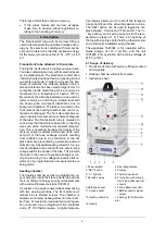
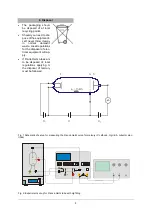
Connect terminals "A", "F" and "K" (refer to fig.
2).
Connect terminal "E" of the Franck-Hertz
tube to the correct input on the control unit by
means of an BNC cable.
Connect the “FH Signal
U
Y
-
out” terminal of
the control unit to the Y input of the oscillo-
scope and terminal “
U
X
” to the X input.
Turn on the control unit and the equipment
should enter ramp mode.
Slowly set a filament voltage of 6 V. The indi-
rectly heated cathode requires about 90 sec-
onds to warm up, once the voltage is applied.
Turn on the heating chamber. Set a tempera-
ture of about 180° C and wait for the tube to
warm up (about 5 to 10 minutes).
Set the minimum acceleration voltage to
zero, slowly increase the maximum accelera-
tion voltage to 80 V.
Do not, however, increase the accelerating
voltage so much that self-discharge no longer
occurs inside the tube. Any ionisation due to
collisions will disrupt the curve.
Set up the oscilloscope initially with settings
of x = 1 V/div and y = 1 V/div.
Observe the emergence of the maxima in the
Franck-Hertz trace on the oscilloscope
screen.
Set up all the parameters, accelerating volt-
age, cathode filament, bias voltage and am-
plitude so that a trace with nicely delineated
maxima and minima is obtained.
The procedure as described so far is a gen-
eral setting procedure. Unavoidable differ-
ences resulting from the manufacture of indi-
vidual Frank-Hertz tubes mean that the opti-
mum parameters may differ from tube to tube.
The test report included with the tube should
give some idea of where good results may be
obtained for the tube in question.
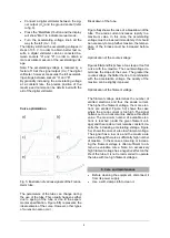
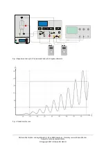
The collector current displays regularly recurring,
equidistant maxima and minima that are inde-
pendent of the accelerating voltage. The interval
between these peaks is 4.9 V. A contact potential
of 2 V exists between the anode and cathode of
the tube, which is why the first maximum only ap-
pears in the region of 7 V. The first maxima will be
more obvious when the temperature of the heat-
ing chamber is lower.
Evaluation of the Franck-Hertz curve:
To fully evaluate the Franck-Hertz curve, a digital
voltmeter is needed. This does not require that
the current of the electron beam be determined
precisely. The oscilloscope screen should show
the trace of a Franck-Hertz curve featuring very
clear maxima and minima.


