4
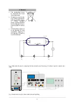
Connect a digital voltmeter between the sig-
nal output (
U
X
) and the ground socket (refer
to fig. 3).
Press the “Man/Ramp” button and the display
will show “Man” to indicate manual mode.
Turn the accelerating voltage knob all the
way to the left (
U
A
= 0 V).
The display will show the accelerating voltages in
steps of 0.5 V. In order to obtain better test re-
sults, a digital voltmeter can be connected be-
tween sockets "A" and "K" in order to obtain a
more accurate measure of the accelerating volt-
age.
Note: The accelerating voltage is reduced by a
factor of 10 at the signal output (
U
X
). The digital
voltmeter, however, measures the full accelerat-
ing voltage
between sockets “A” and “K”.
By gradually increasing the accelerating voltage
at a constant rate, the precise position of the
maxima and minima can be determined with the
aid of the digital voltmeter.
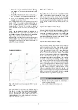
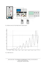
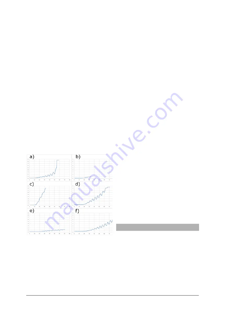
Curve optimization
Fig. 5: Illustration of various signals of the Franck-
Hertz tube.
The parameters of the tube can change during
the use of the tube. This usually happens either
due to ageing of the tube or due to the experi-
mental specification. Figure
5.f)
represents the
ideal example of the curve. However, other types
of curves can also occur.
Breakdown of the tube:
Figure
5.a)
shows the case of a breakdown of the
tube. The anode current increases rapidly to a
maximum value. In this case, the accelerating
voltage must be lowered immediately. If it should
be necessary to map further maxima, the temper-
ature of the furnace must be increased before-
hand.
Optimization of the countervoltage:
Figures
5.b)
and
5.c)
show a too steep or too flat
curve with few maxima. The countervoltage de-
termines the slope of the curve. The greater the
countervoltage, the flatter the rise. In combination
with the acceleration voltage, the quality of the
maxima can be slightly improved.
Optimization of the filament voltage:
The filament voltage determines the number of
emitted electrons and thus the anode current.
The higher the filament voltage, the more elec-
trons are emitted. Figure 5.d) shows the case
where the anode current is too high. The signal
flattens out to a horizontal line above a threshold
value. The maximum number of available elec-
trons is reached (under the given filament volt-
age) and the anode current remains constant, de-
spite the increasing accelerating voltage. Figure
5.e) shows the case of a too low filament voltage.
The signal has a low rise and the maxima are
weak, although there is a sufficiently high number
of maxima. In these cases, lowering or increas-
ing the filament voltage is often sufficient to ob-
tain an evaluable curve. Note: An excessively
high filament voltage has a negative effect on the
life of the tube. It is not recommended to operate
the tube with too high filament voltages.
5. Care and maintenance
Before cleaning the equipment, disconnect it
from its power supply.
Use a soft, damp cloth to clean it.


