background image


Confirm by pressing the 

Date/Time


 but-

ton.  


8.4 Application as a handheld device for 

measuring current and voltage  


Set up the 3B NET

log

™ equipment.  


Connect the voltage/current input of chan-
nel A or B, as desired.  


If necessary, disconnect any sensor which 
might be connected to the same channel.  

Setting and selecting measurement parame-
ters:  


Press the 

Channel


 button (the menu 

DISPLAY SIGNAL 1 will appear on the 
display).  


Select the desired measurement parame-
ter with the 

Rate


 or 

Store


 button.  


Select the mode of operation with the 

Date/Time


 button (the menu RANGE 

SIGNAL 1 will appear on the display).  


Select the desired mode of operation with 
the 

Rate


 or 

Store


 button.  


Confirm this selection with the 

Date/Time


button (the menu DISPLAY SIGNAL 2 will 
appear on the display).  


Select the desired measurement parame-
ter with the 

Rate


 or 

Store


 button.  


Select the desired mode of operation with 
the 

Rate


↑ 

or 

Store


 button.  


Confirm the selection with the 

Date/Time


↵ 

button (a dot will appear in 

front of the respective measurement pa-
rameter when operating manually).  

The 3B NET

log

™ device is ready to conduct 

measurements.  


8.5  Application as  a handheld measuring 

device with sensors  


Set up the 3B NET

log

™ equipment.  


Connect the sensor to the relevant input 
and remove the connections of the 4-mm 
sockets from the same channel.   

After the automatic sensor detection PROBE 
DETECT… has been completed, the 
3B NET

log

™ equipment is ready to conduct 

measurements.   


8.6  Setting the sampling rate   


Press the 

Rate


 button (the options list for 

SAMPLE RATE will appear).  


Select the desired sampling rate with the 

Rate


 or 

Store


 button.  


Press the 

Date/Time


 button (the settings 

STORE ANALOGUE INPUT 1, STORE 
ANALOGUE INPUT 2 and STORE BI-
NARY INPUTS will appear in succession).  


Select YES or NO for each setting with the 

Rate


↑ 

or 

Store


 button and confirm with 

the 

Date/Time


 button (the subsequent 

setting will appear after each confirmation).  


8.7 Data logger  

In data logger mode, the 3B NET

log

™ equip-

ment records the data with a pre-selected 
sampling rate and saves it internally. After 
completing a measurement, the data can be 
transferred onto a computer for evaluation.  


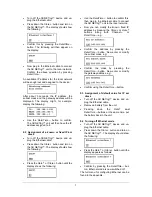
Calling up data logger mode:  


Press the 

Store


 button (STORE will ap-

pear with 

 START

 or 

 CLEAR 


START displayed).  


Starting data logger:  

When the display shows 

 START

:  


Start recording data with the 

Date/Time


button (“BUSY 

 STOP” will appear in the 

display and the measurement begins).   


Stopping the data logger:  

When the display shows 

 STOP:  


Stop recording data by pressing the 

Date/Time


 button (

 CLEAR 

 START 

will appear in the display).  


Clearing data logger:  

When the display shows 

 CLEAR:  


Press the 

Rate


 button (MEM.CLEAR? 


YES will appear in the display).  


Confirm by pressing the 

Date/Time


 but-

ton.  


Exiting data logger mode:  

When the display shows 

 CLEAR 

 START:  


Press the Channel 

 button. 


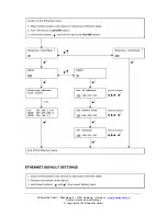
9. Use of Ethernet port 

In order to connect the 3B NET

log™

 unit into a 

local network using its Ethernet port, carry out 
the following procedure:  


9.1 Assignment of an IP address by the 

router 

Summary of Contents for 3B Netlog 1000009

Page 1: ...og device does not come into contact with water The 3B NETlog device should not be exposed to temperatures above 80 C The operating voltage input is protected against polarity reversal However it is not protected against excess voltage Do not apply voltage in excess of 4 5V to the operating voltage input Use of the Ethernet port requires a power sup ply of higher power rating When using the 3B NET...

Page 2: ...4 1 Analogue inputs Voltage inputs channels A and B Measuring equipment 2 Differential amplifi ers Measuring range 200mV 2V 20V Surge voltage protection Max 40V Connections 4 mm safety sockets Current input channel A Measuring range 200mA 2A Excess current protection Max 2 5A Connections 4 mm safety sockets Sensor inputs channels A and B Sensor type Analogue Sensor identification Automatic Sensor ...

Page 3: ...y lighting on and off briefly press the button Date Time button Switching on the battery and temperature displays Switching on the time display Switching on the date display Selection of operating mode manual or automatic Confirming the display Store button Communication to data logger Scrolling down the menu Selecting Yes or No Confirming the display Rate button Selection of sampling rate Scrolli...

Page 4: ...ia a computer never press the buttons on the 3B NETlogTM console 7 1 Driver installation Before installing the 3B NETlab software it is important to install the USB driver Insert the installation CD into the CD ROM drive of the computer Connect 3B NETlog to the computer via the USB cable The computer reports that it has detected a new hardware Windows XP Do not activate Windows Update Select Insta...

Page 5: ...er Click Yes to confirm that the file should be overwritten 7 2 Software installation Note on installing the software For this software please refer to the installa tion instructions available in the 3B NETlab software manual 8 Operating without a computer Operating a 3B NETlog device without a computer is achieved by using the buttons on the operating panel The functions of these buttons may chan...

Page 6: ...NETlog equipment is ready to conduct measurements 8 6 Setting the sampling rate Press the Rate button the options list for SAMPLE RATE will appear Select the desired sampling rate with the Rate or Store button Press the Date Time button the settings STORE ANALOGUE INPUT 1 STORE ANALOGUE INPUT 2 and STORE BI NARY INPUTS will appear in succession Select YES or NO for each setting with the Rate or St...

Page 7: ... button until the display shows the following Use the Date Time button to confirm this then plug in the Ethernet cable to connect the 3B NETlog unit to the local network Now you can modify the known fixed IP address by pressing the Store or Rate buttons along with Channel or Date Time e g Confirm the address by pressing the Date Time button Now enter or modify the subnet mask e g Confirm the mask ...

Page 8: ...since the beginning of the read opera tion Time remaining shows the approximate time remaining for the read operation Options the following settings can be made here Decimal separator sets the decimal separa tor which is used in exported files Date Time format specifies the time and date format which is used in exported measurement files List left shows the acquired data List right additional sele...

Page 9: ...to search and install older firmware versions 12 Format of exported files Exported files have the following format the words shown here between the delimiters are simply placeholders for actual data Entries are separated by tab characters Depending on the settings some columns may be omitted Date Time Inputs Measurement modes Sampling rate Number of measurement re cords Index tab Absolute date tim...

Page 10: ...oype tested EN 61326 1 Tested for noise immunity and interference Conformity with EU guidelines is indicated by the CE marking on the device 16 Licence 3B Netlog and 3B Netlab are registered trademarks of 3B Scientific GmbH in Germany and other countries The 3B Netlab computer program is pro tected by worldwide copyright It may be used exclusively for educational purposes in schools and educationa...

Page 11: ...3B Scientific GmbH Rudorffweg 8 21031 Hamburg Germany www 3bscientific com Subject to technical modifications Copyright 2014 3B Scientific GmbH ...

Page 12: ......

Reviews: