

5
Instruction sheet
3B SCIENTIFIC
3B SCIENTIFIC
3B SCIENTIFIC
3B SCIENTIFIC
3B SCIENTIFIC
®
PHYSICS
PHYSICS
PHYSICS
PHYSICS
PHYSICS
U10362 Ballistic pendulum
®
9/04 MH
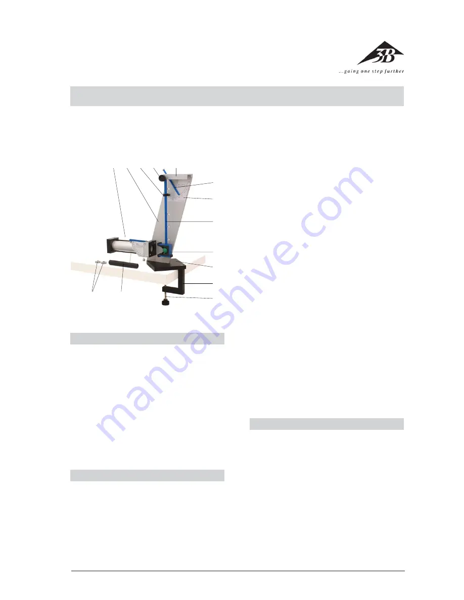
1
Projectile launcher (U10360)
2
Back plate
3
Guide for swing pointer
4
Bearing screw
5
Counter bearing
6
Swing pointer
7
Angle scale
8
Pendulum
9
Projectile catcher
bl
Base plate
bm
Table clamp
bn
Knurled screw
bo
Ramrod (for U10360)
bp
Extra weights, 2 pcs.
1 2 3 4
5
6
7
8
9
bl
bm
bn
Fig. 1: Components
bp
bo
1. Safety instructions
•
This instruction sheet is concerned mainly with the
ballistic pendulum. You should also read the in-
structions for the projectile launcher U10360.
•
To check whether a projectile is located in the pro-
jectile launcher and the spring is cocked, only use
the observation holes at the sides. Do not look into
the barrel from the front. Risk of injury!
•
Never aim at people!
•
Protective goggles should be worn during the ex-
periments.
•
The projectile launcher should always be stored
with the spring loose and with no projectile in the
barrel.
2. Description
•
The ballistic pendulum is for experiment-based
determination of the launch velocity of a projec-
tile when it leaves the projectile launcher. It is also
possible to determine trajectories when the pro-
jectile is launched horizontally or at an angle.
Launch heights of 5, 10, 15, 20 or 30 cm can be
selected easily with the aid of the drilled holes.
•
Thanks to the extreme lightness of the pendulum,
the experiment can be performed using compara-
tively safe plastic projectiles instead of steel balls.
Experiments involving inelastic collisions (quanti-
tatively) and elastic collisions (qualitatively) can be
evaluated. The velocity of the projectiles deter-
mined from trajectory and pendulum experiments
typically agree to within about 3%.
•
Extra weights allow various pendulum travels to
be investigated for constant speeds.
3. Operation and maintenance
•
First the ballistic pendulum is screwed to a stable
bench by means of its clamp. The projectile
launcher is then screwed to the back plate
2
rom
behind either in a horizontal position in front of
the pendulum as in Fig. 1 or as shown in Fig 3.
Tip:
if the workbench is not stable enough, it may
be that when the pendulum swings to its maximum
extent and then swings back, it may jog the appa-
ratus when striking the projectile launcher, caus-
ing the swing pointer to be shifted out of line. If
this happens, the pendulum should rather be
stopped by hand.
•
Projectiles should always be loaded when the sp-
ring is not under tension by placing the sphere in
loosely through the front of the plastic cylinder


