


2
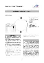
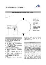
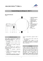
through a micro-mesh nickel grating situated at the
aperture of the gun. Onto this grid, a thin layer of
polycrystalline graphitised carbon has been depos-
ited by vaporisation. This layer affects the electrons
in the beam much like a diffraction grating. The
result of this diffraction is seen in the form of an
image comprising two concentric rings that be-
come visible on the fluorescent screen. A spot re-
sulting from the undeflected electron beam con-
tinues to be visible at the centre of the rings.
A magnet is also supplied with the tube. This allows
the direction of the electron beam to be changed,
which may be necessary if the graphite target has
slight damage as a result of the manufacturing
process or due to later overheating.
3. Technical data
Filament voltage:
≤
7,5 V AC/DC
Anode voltage:
0 – 5000 V DC
Anode current:
typ. 0,15 mA bei 4000 V
DC
Lattice constant of graphite:
d
10
= 0.213 nm
d
11
= 0.123 nm
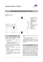
Dimensions:
Distance from graphite target
to fluorescent screen:
135 mm approx.
Fluorescent screen:
100 mm dia. approx.
Glass bulb:
130 mm dia. approx.
Total length:
260 mm dia. approx.
4. Operation
To perform experiments using the electron diffrac-
tion tube, the following equipment is also re-
quired:
1 Tube holder D
U19100
1 High voltage power supply 5 kV
U33010-115
or
1 High voltage power supply 5 kV
U33010-230
1 Analogue multimeter AM51
U17451
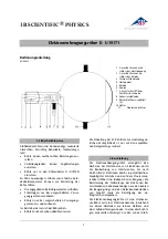
4.1 Setting up the tube in the tube holder
•
The tube should not be mounted or removed
unless all power supplies are disconnected.
•
Push the jaw clamp sliders on the stanchion of
the tube holder right back so that the jaws
open.
•
Push the bosses of the tube into the jaws.
•
Push the jaw clamps forward on the stanchions
to secure the tube within the jaws.
4.2 Removing tube from the tube holder
•
To remove the tube, push the jaw clamps right
back again and take the tube out of the jaws.
4.3 General instructions
The graphite foil on the diffraction grating is only a
few layers of molecules thick and any current
greater 0.2 mA can cause its destruction.
The internal resistor is there to prevent damage to
the graphite foil.
The anode voltage and the graphite target itself
should be monitored throughout the experiment. If
the graphite target starts to glow or the emission
current rises above 0.2 mA, the anode must imme-
diately be disconnected from its power supply
If the diffraction rings are not satisfactorily visible,
the electron beam can be redirected by a magnet
so that it passes through an undamaged region of
the target.
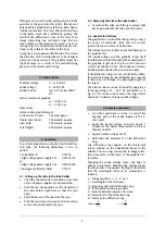
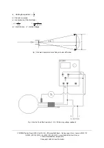
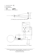
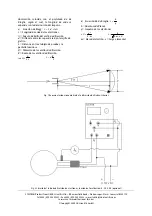
The electron beam can be focussed by applying a
focussing voltage of 0 – 50 V DC (connected as in
Fig. 2). This can be used to make the rings clearer
and easier to observe at lower anode voltages.
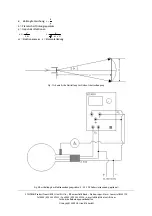
5. Example experiment
•
Set u the experiment as in Fig. 2. Connect the
negative pole of the anode supply via the 2-
mm socket.
•
Apply the heater voltage and wait about 1
minute for the heater temperature to achieve
thermal stability
•
Apply an anode voltage of 4 kV.
•
Determine the diameter
D
of the diffraction
rings.
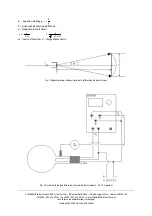
Two diffraction rings appear on the fluorescent
screen centred on the undeflected beam in the
middle. The two rings correspond to Bragg reflec-
tions from atoms in the layers of the graphite crys-
tal lattice.
Changing the anode voltage causes the rings to
change in diameter. Reducing the voltage makes
the rings wider. This supports de Broglie's postulate
that the wavelength increases as momentum is
reduced.
a)
Bragg equation:
ϑ
⋅
⋅
=
λ
sin
d
2
λ
= wavelength of the electrones
ϑ
= glancing angle of the diffraction ring
d
= lattice plane spacing in graphite
L
= distance between sample and screen
D
= diameter
D
of the diffraction ring
R
= radius of the diffraction ring
L
D
tan
⋅
=
ϑ
2
2
L
R
d
⋅
=
λ


