background image


3-37 

Table 3-29 

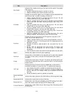
MAC Based ACL Setup Page item description 

Item 

Description 

Selection ACL 

Selects an existing MAC-based ACL to which rules are to be added. 

Create ACL 

Defines a new user-defined MAC-based Access Control List. The options 
are as follows: 

z


ACL Priority: Sets the ACL priority. The possible field values are 1-100. 

z


Rule Priority Type: Sets the rule priority type. CONFIG: You will have to 
configure the ACL rule priority by yourself, AUTO: the ACL rule priority 
will be configured automatically. 

Priority 

Sets the rule priority, which determines which rule is matched to a packet on 
a first-match basis. The possible field values are 1-65535. 

Source MAC 
Address 

Matches the source MAC address to which packets are addressed to the 
rule. 

Source Mask 

Defines the source MAC Address wildcard mask.  

Wildcards are used to mask all or part of a source MAC address. Wildcard 
masks specify which bits are used and which are ignored. A wildcard mask 
of FF:FF:FF:FF:FF:FF indicates that no bit is important. A wildcard of 
00.00.00.00.00.00.00 indicates that all bits are important. 

For example, if the source MAC address is 00:AB:22:11:33:00 and the 
wildcard mask is 00:00:00:00:00:FF, the first five bytes of the MAC are used, 
while the last byte is ignored. For the source MAC address 
00:AB:22:11:33:00, this wildcard mask matches all MAC addresses in the 
range 00:AB:22:11:33:00 to 00:AB:22:11:33:FF. 

Destination MAC 
Address 

Matches the destination MAC address to which packets are addressed to the 
rule. 

Destination Mask 

Defines the destination MAC Address wildcard mask.  

Wildcards are used to mask all or part of a destination MAC address. 
Wildcard masks specify which bits are used and which are ignored. A 
wildcard mask of FF:FF:FF:FF:FF:FF indicates that no bit is important. A 
wildcard mask of 00.00.00.00.00.00 indicates that all bits are important. 

For example, if the destination MAC address is 00:AB:22:11:33:00 and the 
wildcard mask is 00:00:00:00:00:FF, the first five bytes of the MAC are used, 
while the last byte is ignored. For the destination MAC address 
00:AB:22:11:33:00, this wildcard mask matches all MAC addresses in the 
range 00:AB:22:11:33:00 to 00:AB:22:11:33:FF. 

VLAN ID 

Matches the packet's VLAN ID to the rule. The possible field values are 1 to 
4094. 

CoS 

Classifies traffic based on the CoS tag value. 

CoS Mask 

Defines the CoS mask used to classify network traffic. 

Ethertype 

Provides an identifier that differentiates between various types of protocols.

Action 

Specifies the ACL forwarding action. In addition, the port can be shut down, 
a trap can be sent to the network administrator, or packet is assigned rate 
limiting restrictions for forwarding. The options are as follows: 

z


Permit: Forwards packets which meet the ACL criteria. 

z


Deny: Drops packets which meet the ACL criteria. 


To create a new MAC-based ACL: 

1)  Select Create ACL. 

2)  Enter the name of the new ACL. 

3) Click 

Create

. The new ACL is created, and the switch is updated. 

Summary of Contents for 2226-SFP Plus

Page 1: ...P Plus Baseline Switch 2426 PWR Plus Baseline Switch 2250 SFP Plus User Guide 3CBLSF26H 3CBLSF26PWRH 3CBLSF50H Part No 10017022 Manual Version 6W107 www 3com com 3Com Corporation 350 Campus Drive Marlborough MA USA 01752 3064 ...

Page 2: ...mmercial license for the Software Technical data is provided with limited rights only as provided in DFAR 252 227 7015 Nov 1995 or FAR 52 227 14 June 1987 whichever is applicable You agree not to remove or deface any portion of any legend provided on any licensed program or documentation contained in or delivered to you in conjunction with this User Guide Unless otherwise indicated 3Com registered...

Page 3: ...y Notices This chapter describes the important regulatory notices for you product 8 List of the Hazardous Substances This chapter lists the Hazardous Substances for you product 9 Glossary This chapter lists the main glossaries for the manual Conventions The manual uses the following conventions Command conventions Convention Description Boldface The keywords of a command line are in Boldface itali...

Page 4: ...ulti level menus are separated by angle brackets For example File Create Folder Symbols Convention Description Means reader be careful Improper operation may cause data loss or damage to equipment Means a complementary description Obtaining Documentation You can access the most up to date 3Com product documentation on the World Wide Web at this URL http www 3com com ...

Page 5: ...ng DHCP 1 11 Manual IP Configuration 1 11 2 Connecting To the Web Interface 2 1 Requirements for Accessing the Web Interface 2 1 Choosing a Web Browser 2 1 Default User and Password 2 2 Logging On to the Web Interface 2 2 Navigating the Web Interface 2 2 Menu 2 2 Buttons 2 5 3 Configuring the Switch 3 1 Configuring System Access 3 1 Defining System Access 3 1 Modifying System Access 3 2 Removing S...

Page 6: ... Queue Algorithm 3 47 Configuring CoS to Queue 3 48 Configuring DSCP to Queue 3 49 Configuring Trust Mode 3 51 Configuring Bandwidth Settings 3 51 Configuring Voice VLAN 3 53 Configuring SNMP 3 58 Defining SNMP Communities 3 58 Removing SNMP Communities 3 59 Defining SNMP Traps 3 59 Removing SNMP Traps 3 60 Configuring LLDP 3 61 LLDP Overview 3 61 Configuring Global LLDP Parameters 3 61 Configurin...

Page 7: ...Issues 4 2 5 CLI Reference Guide 5 1 Getting Started with the Command Line Interface 5 1 Prerequisites 5 1 Logging on to the CLI 5 1 CLI Features 5 2 Online Help 5 2 Command History 5 3 Error Messages 5 3 Command Edit 5 4 CLI Configuration 5 4 display ip 5 4 display management vlan 5 5 display version 5 6 ip address 5 6 ip address dhcp alloc 5 6 ip gateway 5 7 localuser 5 7 management vlan 5 8 man...

Page 8: ...iv ICES Statement 7 1 CE Statement Europe 7 1 VCCI Statement 7 2 CCC Statement 7 2 8 List of the Hazardous Substances 8 1 9 Glossary 9 1 ...

Page 9: ...dware Features z Front View Detail z LED Status Indicators z System Specifications Overview of the Switch z The Baseline Switch 2226 SFP Plus is a versatile easy to use configurable switch z The Baseline Switch 2426 PWR Plus is a versatile easy to use configurable Power over Ethernet PoE Switch z The Baseline Switch 2250 SFP Plus is a versatile easy to use configurable switch Each Switch is ideal ...

Page 10: ...ort is disabled The 1000 Mbps connections can only operate in full duplex mode Mounting 19 inch rack or standalone mounting Fanless design supported by Baseline Switch 2226 SFP Plus and Baseline Switch 2250 SFP Plus Silent operation whether used in a rack or desktop situation PoE Only supported by Baseline Switch 2426 PWR Plus Each RJ 45 port supports the IEEE 802 3af PoE standard Any 802 3af comp...

Page 11: ...ing data Yellow The port works at the rate of 10 Mbps the LED flashes quickly when the port is sending or receiving data 10 100BASE T port OFF The link has not been established either nothing is connected to the port or there is a problem z Check that the attached device is powered on z Check that the cable is the correct type and is not faulty If these checks do not identify the cause of the prob...

Page 12: ...e is not inserted or is not recognized Green The port is supplying power to the device connected to it PoE Power Only supported by Baseline Switch 2426 PWR Plus OFF The port is not supply power to the device connected to it or not connected System Specifications Table 1 3 contains the system specifications of the Switch Table 1 3 System specifications of the Switch Specification 2226 SFP 2426 PWR ...

Page 13: ...ollowing for all units z One product sealed in a plastic bag z One CD z One Safety and Regulatory Information manual z One Installation Guide LAT Spanish and Portuguese only z One warranty card z One Mounting Kit z One DB 9 to RJ 45 cable Positioning the Switch The switch is suitable for use in an office environment where it can be free standing or mounted in a standard 19 inch equipment rack Alte...

Page 14: ...ounting kit or it can be free standing Do not place objects on top of the unit or stack If installing the switch in a free standing stack of different size Baseline or Super stack 3 units the smaller units must be installed above the larger ones Do not have a free standing stack of more than six units Using the Mounting Kit The switch is supplied with two mounting brackets and four screws These ar...

Page 15: ...other ensuring that the pads of the upper unit line up with the recesses of the lower unit Supplying Power to the Switch Power problems can be the cause of serious failures and downtime in your network Ensure that the power input to your system is clean and free from sags and surges to avoid unforeseen network outages 3Com recommends that you install power conditioning especially in areas prone to...

Page 16: ... cord is connected correctly and then try powering on the switch again z If the switch still does not operate contact your 3Com network supplier If POST fails try the following z Power off the switch and then power it on again Check the Power LED and see if POST was successfully completed z Reset the switch See Resetting to Factory Defaults Resetting the switch to its factory default erases all yo...

Page 17: ...or 1000BASE LX media type z 1000BASE SX SFP transceiver Use this transceiver to connect the switch directly to a multimode fiber optic cable z 1000BASE LX SFP transceiver Use this transceiver to connect the switch directly to a single mode fiber optic cable or to multi mode fiber using a conditioned launch cable To activate the SFP port 1 Hold the transceiver so that the fiber connector is toward ...

Page 18: ...elease the catch mechanism The SFP transceiver should slide out easily Performing Spot Checks At frequent intervals you should visually check the switch Regular checks can give you an early warning of a possible failure any problems can then be attended to when there will be least effect on users 3Com recommends periodically checking the items listed in Table 1 5 Table 1 5 Items to Check Item Oper...

Page 19: ...o view the automatically allocated IP Information through the Console Port see CLI Reference Guide Manual IP Configuration When you configure the IP information manually the switch remembers the information that you enter until you change it again You should use the manual IP configuration method if z You do not have a DHCP server on your network or z You want to remove the risk of the IP address ...

Page 20: ...sing a Category 5 twisted pair Ethernet cable with RJ 45 connectors z Ensure that you know your switch s IP address See Configuring IP Address z Check that your management workstation is on the same subnet as your switch z Choose a suitable Web browser Choosing a Web Browser To display the Web interface correctly use one of the following Web browsers and platform combinations Table 2 1 Supported W...

Page 21: ...d enter the IP address of the switch that you wish to manage in the URL locator For example in the following format http xxx xxx xxx xxx The Login Page appears Figure 2 1 Login Page 2 Enter admin as your user name and leave the password field blank 3 Click Login The main Web interface page is displayed Navigating the Web Interface The Web interface has been designed to enable you to easily perform...

Page 22: ... address of its neighbors is known Backup Restore Allows you to backup and restore the switch s configuration Firmware Upgrade Allows you to upgrade the current firmware via HTTP Reset Allows you to reset the switch to factory default settings System Access Contains tabs that allow you to z Display user summary information z Create a new user z Modify existing users z Remove existing users System ...

Page 23: ...igures the ACL MAC Based ACL Configures MAC Based ACL on the switch IP Based ACL Configures IP Based ACL on the switch ACL Binding Configures ACL Binding on the switch QoS Configures QoS settings CoS Contains tabs that allow you to z Displays CoS default settings assigned to ports z Defines CoS Queue Configures Queue Setting CoS to Queue Displays and defines CoS to Queue DSCP to Queue Contains fie...

Page 24: ...splay detailed information per port z Configure system authentication settings Address Table Displays MAC address table information for ports and VLANs Port Mirroring Monitor traffic going in or out of ports Monitoring Cable Diagnostics Contains tabs that allow you to z Display selected cable diagnostics information for all ports z Display all cable diagnostics information for a single port Help D...

Page 25: ...er with read write access rights There is always one management level user configured for the switch z Monitor access level Provides the user with read only system access rights This section contains the following topics z Defining System Access z Modifying System Access z Removing System Access z Viewing System Access Settings To ensure that unauthorized users do not access the Web interface 3Com...

Page 26: ...he System Access Modify Page allows network administrators to modify users passwords and access levels for users using the System Access Interface Click Administration System Access Modify The System Access Modify Page opens Figure 3 2 System Access Modify Page The System Access Modify Page contains the following fields Table 3 2 System Access Modify Page item description Item Description Access L...

Page 27: ...ration System Access Remove The System Access Remove Page opens Figure 3 3 System Access Remove Page Viewing System Access Settings The System Access Summary Page displays the current users and access levels defined on the switch Click Administration System Access Summary The System Access Summary Page opens Figure 3 4 System Access Summary Page The System Access Summary Page contains the followin...

Page 28: ... static IP address Click Administration IP Setup The IP Setup Page opens Figure 3 5 IP Setup Page The IP Setup Page contains the following fields Table 3 4 IP Setup Page item description Item Description Configuration Method Defines whether the IP address is configured statically or dynamically The possible field values are z Static Specifies that the IP address is configured by the user z DHCP Sp...

Page 29: ...ngs Setup Page The ARP Settings Setup Page contains the following fields Table 3 5 ARP Settings Setup Page item description Item Description Interface Indicates the management VLAN VLAN 1 for which ARP parameters are defined IP Address Defines the static IP address which is associated with the static MAC address MAC Address Defines the static MAC address which is associated with the static IP addr...

Page 30: ...tatic ARP entries Interface Indicates the VLAN for which ARP parameters are defined IP Address Indicates the IP address which is associated with the MAC address MAC Address Displays the MAC address which is associated in the ARP table with the IP address Status Displays the ARP table entry type Possible field values are z Dynamic Indicates the ARP entry is learned dynamically z Static Indicates th...

Page 31: ...ressed to a destination stored in one of the databases is forwarded immediately to the port The Dynamic Address Table can be sorted by interface VLAN and MAC address MAC addresses are dynamically learned as packets from sources arrive at the switch MAC addresses are associated with ports by learning the ports from the frames source address Frames addressed to a destination MAC address that is not ...

Page 32: ...LAN ID No Aging Marks the aging status of the MAC address assigned by the user The possible values are z Checked Indicates that the Address Table entry assigned by the user is not aged out z Unchecked Indicates that the Address Table entry assigned by the user is aged out Defining Aging Time The Address Table Aging Time Setup Page allows the network manager to define the Address Table Aging Time T...

Page 33: ...Port Remove The Port Remove Page opens Figure 3 11 Port Remove Page 1 Select a port to remove MAC Addresses 2 Select entries from the address table to be removed 3 Click Remove Removing MAC Addresses from the Address Table The Address Table Remove Page allows the network manager to remove current MAC addresses from the Address Table Click Monitoring Address Table Remove The Address Table Remove Pa...

Page 34: ...y learned MAC addresses MAC Address Displays the current MAC addresses listed in the MAC address table filtered by the selected value of the State field VLAN ID Displays the VLAN ID associated with the port and MAC address State Displays the MAC address configuration method Possible values are z Config Static Displays the statically configured MAC address z Config Dynamic Displays the dynamically ...

Page 35: ...MAC address State Displays the MAC address configuration method Possible values are z Config Static Displays the statically configured MAC address z Config Dynamic Displays the dynamically learned MAC address Port Index Displays the port through which the address was learned Aging Time Displays that the MAC address is aged out or not Possible values are z NOAGED Indicates that the MAC address is n...

Page 36: ...z No Change Retains the current flow control status on the port z Enabled Enables flow control on the port z Disabled Disables flow control on the port Speed Specifies the configured rate for the port The port speed determines what speed setting options are available Port speeds can only be configured when auto negotiation is disabled The possible field values are z No Change Retains the current p...

Page 37: ...ctions are only available for 10 Mbps and 100 Mbps settings Viewing Port Settings The Port Summary Page permits the network manager to view the current configuration for all the ports Click Port Administration Summary The Port Summary Page opens Figure 3 16 Port Summary Page The Port Summary Page contains the following fields Table 3 12 Port Summary Page item description Item Description State Ind...

Page 38: ...port z Full The interface supports transmission between the switch and its link partner in both directions simultaneously z Half The interface supports transmission between the switch and the client in only one direction at a time PVID Indicates VLAN ID of this port for untagged packets Viewing Port Details The Port Detail Page displays the current port configuration for specific ports Click Port ...

Page 39: ...ide 30W power for access device max PoE Mode for selected enabled ports Defines the PoE mode for the selected port Guarantee Power Summary Displays guaranteed and total PoE power z Total PoE Available The total amount of PoE power that can be provided by the switch z Guarantee PoE The maximum amount of PoE power that has been guaranteed for selected ports This value is defined by the number of por...

Page 40: ...ates the amount of additional power currently available to the switch The field value is displayed in Watts State Indicates if the port is enabled to deliver power to powered devices The possible field values are z Enable Indicates the switch is delivering power This is the default z Disabled Indicates the switch is not delivering power Mode Indicates the port power mode The possible field values ...

Page 41: ...atistics are displayed Received Bytes Octets Displays the number of octets received on the interface since the switch was last refreshed This number includes bad packets and FCS octets but excludes framing bits Received Packets Displays the number of packets received on the interface including bad packets Multicast and broadcast packets since the switch was last refreshed Broadcast Packets Receive...

Page 42: ...received on the interface since the switch was last refreshed Configuring VLAN VLANs are logical subgroups with a Local Area Network LAN which combine user stations and network devices into a single unit regardless of the physical LAN segment to which they are attached VLANs allow network traffic to flow more efficiently within subgroups VLANs use software to reduce the amount of time it takes for...

Page 43: ...Description Create VLANs Enter ID of configured VLANs Create Creates the VLAN ID s ID Displays the VLAN ID Name Displays the user defined VLAN name Modifying VLAN The Modify VLAN Page allows the network manager to change VLAN membership At least one port must always be an untagged member of VLAN 1 the management VLAN If you choose to connect all ports to VLANs other than VLAN 1 you will no longer ...

Page 44: ... A Member Indicates the interface is not a member of the VLAN z Not available for selection Indicates the interface is not available for selection Untagged membership Indicates the port is an untagged member of the VLAN Tagged membership Indicates the port is a tagged member of a VLAN VLAN tagged frames are forwarded by the interface The frames contain VLAN information By default all ports belong ...

Page 45: ...rames are forwarded by the interface The frames contain VLAN information z Not A Member Indicates the interface is not a member of the VLAN z Not available for selection Indicates the interface is not available for selection VLAN ID Defines the VLAN ID to which the port is to be assigned Renaming VLANs The VLAN Rename Page allows the network manager to select a VLAN from the list to be renamed Cli...

Page 46: ... Details The VLAN Detail Page provides information and global parameters on VLANs configured on the system Click Device VLAN VLAN Detail The VLAN Detail Page opens Figure 3 26 VLAN Detail Page The VLAN Detail Page contains the following information ...

Page 47: ... a member untagged or tagged of that VLAN the frame is accepted Otherwise if the port is not a member of that VLAN the frame is discarded z When a port receives an untagged frame and the port is an untagged member of a VLAN the frame is accepted and assigned to that VLAN ID Otherwise if the port is not an untagged member of any VLAN the frame is discarded The switch will only forward a frame to po...

Page 48: ...ority port number and operation key After receiving the information from the sender the receiver compares it with the locally saved information about other ports chooses member ports for the aggregation group and reaches agreement about whether a port can join or leave a dynamic aggregation group During link aggregation LACP generates a configuration mix according to the port configuration rate du...

Page 49: ...an receive send LACP protocol packets z Only the selected ports can receive send service packets the unselected ports cannot In a static aggregation group the system sets the ports to selected or unselected state according to the following rules z Among the ports in an aggregation group that are in up state the system determines the master port with one of the following settings being the highest ...

Page 50: ...up ID Defines the group ID Manual Defines Manual Aggregation Static Defines Static LACP Aggregation To create a new link aggregation group 1 Enter a LAG ID in the box field 2 Select Link Aggregation Type Manual or Static 3 Select the ports to add to the group 4 Click Apply Modifying Link Aggregation The Link Aggregation Modify Page allows network managers to select or deselect port for the specifi...

Page 51: ...k Aggregation Remove The Link Aggregation Remove Page opens Figure 3 30 Link Aggregation Remove Page Viewing Link Aggregation The Link Aggregation Summary Page displays the state of the current link aggregation Click Port Link Aggregation Summary The Link Aggregation Summary Page opens Figure 3 31 Link Aggregation Summary Page The Link Aggregation Summary Page includes the following fields ...

Page 52: ...e Link Aggregation Modify Page opens Figure 3 32 Link Aggregation Modify Page The Link Aggregation Modify Page contains the following fields Table 3 23 Link Aggregation Modify Page item description Item Description LACP System Priority Specifies system priority value The default value is 32768 The field range is 0 65535 LACP Port Priority Specifies the LACP priority value for the port The default ...

Page 53: ...e operational z Enabling redundant paths if the main paths fail Spanning tree uses a distributed algorithm to select a bridging device that serves as the root of the spanning tree network The bridging device known as the Root Bridge generates bridge protocol data units BPDUs on all ports at a regular interval known as the Hello Time All other spanning tree compliant devices on the network have a d...

Page 54: ...thout creating forwarding loops While Classic STP prevents Layer 2 forwarding loops in a general network topology convergence can take between 30 60 seconds This section contains the following topics z Defining STP Global Parameters z Modifying STP Interface Parameters z Viewing STP Defining STP Global Parameters The STP Global Setup Page allows network managers to assign STP global settings Click...

Page 55: ...eld range is 0 61440 The default value is 32768 The port priority value is provided in increments of 4096 Hello Time Specifies the switch Hello Time The Hello Time indicates the amount of time in seconds a Root Bridge waits between configuration messages The default is 2 seconds Max Age Specifies the switch Maximum Age Time The Maximum Age Time is the amount of time in seconds a bridge waits befor...

Page 56: ...e port is automatically placed in the Forwarding state when the port link is up Fast Link optimizes the STP protocol convergence STP convergence takes 30 seconds and is not dependent on the number of switches in the network The possible field values are z No Change Retains the current port status z Enabled Indicates fast link is enabled on the port z Disabled Indicates fast link is disabled on the...

Page 57: ...oint link This is the default value z Point to Point Indicates if a Point to Point link is currently established on the port Ports set to Full Duplex modes are considered Point to Point port links z Shared Enables the switch to establish a shared link Viewing STP The STP Summary Page displays the current STP parameters for all ports Click Device Spanning Tree Summary The STP Summary Page opens Fig...

Page 58: ...h is attached to the LAN z Alternate Provides an alternate path to the root switch from the root interface z Backup With the designated port being blocked the backup port becomes the new designated port fast and begins to forward data seamlessly z Root Provides the lowest cost path to forward packets to the root switch Speed Indicates the speed at which the port is operating Path Cost Indicates th...

Page 59: ...fining IGMP Snooping The IGMP Snooping Setup Page allows network managers to define IGMP Snooping parameters for VLANs Click Device IGMP Snooping Setup The IGMP Snooping Setup Page opens Figure 3 37 IGMP Snooping Setup Page The IGMP Snooping Setup Page contains the following fields Table 3 28 IGMP Snooping Setup Page item description Item Description IGMP Snooping Status Defines whether IGMP Snoop...

Page 60: ... for specific ingress ports A network manager can configure an ACL on an ingress port so that packets are either admitted or denied entry The user can also specify that when packets are denied entry the ingress port is also disabled This section includes the following topics z Configuring MAC Based ACL z Configuring IP Based ACL z Configuring ACL Binding Configuring MAC Based ACL This section incl...

Page 61: ... 00 to 00 AB 22 11 33 FF Destination MAC Address Matches the destination MAC address to which packets are addressed to the rule Destination Mask Defines the destination MAC Address wildcard mask Wildcards are used to mask all or part of a destination MAC address Wildcard masks specify which bits are used and which are ignored A wildcard mask of FF FF FF FF FF FF indicates that no bit is important ...

Page 62: ...age opens Figure 3 39 MAC Based ACL Modify Page The description of parameters in the page refers to Defining MAC Based ACL 1 Selects the ACL to be modified 2 Selects the Rule to be modified 3 Modifies the fields of the Rule 4 Click Apply Removing MAC Based ACL The MAC Based ACL Remove Page allows the network administrator to remove MAC based ACL or MAC based ACL rules Click Device ACL MAC Based AC...

Page 63: ...C Based ACL configured on the switch Click Device ACL MAC Based ACL The MAC Based ACL Summary Page opens Figure 3 41 MAC Based ACL Summary Page The MAC Based ACL Summary Page contains the following fields Table 3 31 MAC Based ACL Summary Page item description Item Description ACL Name Contains a list of the MAC based ACL ACL Priority Indicates the ACL Priority Priority Indicates the rule priority ...

Page 64: ...d ACL Defining IP Based ACL The IP Based ACL Setup Page allows network managers to define IP Based ACL Click Device ACL IP Based ACL Setup The IP Based ACL Setup Page opens Figure 3 42 IP Based ACL Setup Page The IP Based ACL Setup Page contains the following fields Table 3 32 IP Based ACL Setup Page item description Item Description Selection ACL Selects an existing IP based ACL to which rules ar...

Page 65: ...z Rst Reset the connection This invalidates the sequence numbers and aborts the session between the sender and receiver z Syn Synchronize Initial Sequence Numbers ISNs This is used to initialize a new connection z Fin Finish This indicates there is no more data from the sender This marks a normal closing of the session between the sender and receiver Source IP Address If selected enables matching ...

Page 66: ...3 IP Based ACL Modify Page The description of parameters in the page refers to Defining IP Based ACL 1 Selects the ACL to be modified 2 Selects the Rule to be modified 3 Modifies the fields of the Rule 4 Click Apply Removing IP Based ACL The IP Based ACL Remove Page allows the network administrator to remove IP based ACL or IP based ACL rules Click Device ACL IP Based ACL Remove The IP Based ACL R...

Page 67: ...opens Figure 3 45 IP Based ACL Summary Page The IP Based ACL Summary Page contains the following fields Table 3 34 IP Based ACL Summary Page item description Item Description ACL Name Contains a list of the IP Based ACL ACL Priority Indicates the ACL Priority Priority Indicates the rule priority which determines which rule is matched to a packet on a first match basis The possible field values are...

Page 68: ...ction In addition the port can be shut down a trap can be sent to the network administrator or packet is assigned rate limiting restrictions for forwarding Configuring ACL Binding This section includes the following topics z Defining ACL Binding z Removing ACL Binding z Viewing ACL Binding Defining ACL Binding The ACL Binding Setup Page allows the network administrator to bind specific ports to MA...

Page 69: ...ption Item Description Remove All Port Binding By ACL Remove all the port binding according to the current ACL ACL Name Displays the name of ACL to be removed from the selected port To remove ACL Binding 1 Select an ACL Name from Remove All Port Binding By ACL or ACL Name 2 Click Remove Viewing ACL Binding The ACL Binding Summary Page displays the user defined ACLs mapped to the interfaces Click D...

Page 70: ...ty queue while other traffic can be assigned a lower priority queue The result is an improved traffic flow for traffic with high demand This section contains information for configuring QoS and includes the following topics z Configuring CoS z Configuring Queue Algorithm z Defining CoS to Queue z Configuring DSCP to Queue z Configuring Trust Mode z Configuring Bandwidth Settings z Configuring Voic...

Page 71: ...Restores the switch factory defaults for CoS values Viewing CoS Settings The CoS Summary Page displays CoS default settings assigned to ports Click Device QoS CoS The CoS Summary Page opens Figure 3 50 CoS Summary Page The CoS Summary Page contains the following fields Table 3 39 CoS Summary Page item description Item Description Port Displays the interface for which the CoS default value is defin...

Page 72: ...h port queue is determined by the weight whose values are 1 2 10 and 15 Configuring CoS to Queue Defining CoS to Queue The CoS to Queue Setup Page contains fields for mapping CoS values to traffic queues Four traffic priority queues are supported on the switch with 1 representing the lowest queue and four as the highest The highest priority queue functions with strict priority while queues 1 3 fun...

Page 73: ...eue Summary Page opens Figure 3 53 CoS to Queue Summary Page The CoS to Queue Summary Page contains the following fields Table 3 42 CoS to Queue Summary Page item description Item Description Class of Service Displays the CoS priority tag values where 0 is the lowest and 7 is the highest Queue Indicates the traffic forwarding queue to which the CoS priority is mapped Four traffic priority queues a...

Page 74: ...es to a traffic forwarding queue DSCP Displays the incoming packet s DSCP value CoS Specifies the CoS value forwarding queue to which the DSCP priority is mapped Viewing DSCP to Queue The DSCP to CoS Summary Page contains a table that displays the DSCP values mapped to CoS values Click Device QoS DSCP to Queue The DSCP to Queue Summary Page opens Figure 3 55 DSCP to Queue Summary Page The DSCP to ...

Page 75: ...item description Item Description Trust Mode Specifies which packet fields to use for classifying packets entering the switch When no rules are defined the traffic containing the predefined packet CoS field is mapped according to the relevant trust modes table Traffic not containing a predefined packet field is mapped to best effort The possible Trust Mode field values are z CoS Classifies traffic...

Page 76: ...t is 3500 1 000 000 kbits per second Enable Egress Shaping Rate Enables setting Egress Shaping Rates Committed Information Rate CIR Defines the CIR for the interface The field range of nomal port is 64 100 000 kbits per second and the field range of combo port is 64 1 000 000 kbits per second Egress Shaping Rates Committed Burst Size CbS Defines the CbS for the interface The field range is 4 096 b...

Page 77: ...fic shaping is disabled for the interface This is the default CIR Indicates the Committed Information Rate CIR for the interface Egress Shaping Rates CbS Indicates the Committed Burst Size CbS for the interface Configuring Voice VLAN Voice VLAN allows network administrators to enhance VoIP service by configuring ports to carry IP voice traffic from IP phones on a specific VLAN VoIP traffic has a p...

Page 78: ... from the Voice VLAN The packet priority derives from the source destination MAC prefix The packet gets higher priority when there is a match with the OUI list Using the OUI network managers can add a specific manufacturer s MAC addresses to the OUI table Once the OUIs are added all traffic received on the Voice VLAN ports from the specific IP phone with a listed OUI is forwarded on the voice VLAN...

Page 79: ...mount of time after the last IP phone s OUI is aged out for a specific port The Voice VLAN aging time starts after the MAC Address is aged out from the Dynamic MAC Address table The port will age out after the bridge and voice aging times The default bridge aging time is 300 seconds The default voice aging time is 1 day The possible fields are z Day The field range is 0 30 z Hour The field range i...

Page 80: ... on the Voice VLAN Port security ensures that packets arriving with an unrecognized MAC address are dropped Port Security is only applicable when Voice VLAN Port Mode is set to Auto z No Changes Maintains the current Voice VLAN port security settings z Enable Enables port security on the Voice VLAN z Disable Disables port security on the Voice VLAN This is the default value Viewing Voice VLAN Port...

Page 81: ...51 Voice VLAN Summary Page item description Item Description Voice VLAN State Indicates if Voice VLAN is enabled on the switch The possible field values are z Enabled Voice VLAN is enabled on the switch z Disabled Voice VLAN is disabled on the switch This is the default value Voice VLAN ID Indicates the Voice VLAN ID number Voice VLAN Aging Time Indicates the amount of time after the last IP phone...

Page 82: ...munities z Removing SNMP Communities z Defining SNMP Traps z Removing SNMP Traps Defining SNMP Communities Access rights are managed by defining communities in the SNMP Communities Setup Page When the community names are changed access rights are also changed SNMP communities are defined only for SNMP v1 and SNMP v2c Click Administration SNMP Communities Setup The SNMP Communities Setup Page opens...

Page 83: ... z Read Write Management access is read write and changes can be made to the switch configuration but not to the community Removing SNMP Communities The SNMP Communities Remove Page allows the system manager to remove SNMP Communities Click Administration SNMP Communities Remove The SNMP Communities Remove Page opens Figure 3 66 SNMP Communities Remove Page To Remove SNMP Communities 1 Select the ...

Page 84: ...unity string of the trap manager Trap Version Defines the trap type The possible field values are z SNMP V1 Indicates that SNMP Version 1 traps are sent z SNMP V2c Indicates that SNMP Version 2 traps are sent Removing SNMP Traps The SNMP Traps Remove Page allows the system manager to remove SNMP Traps Click Administration SNMP Traps Remove The SNMP Traps Remove Page opens Figure 3 68 SNMP Traps Re...

Page 85: ...fall into these categories basic TLVs organizationally specific TLVs and media endpoint discovery MED related TLVs Basic TLVs are the base of network device management Organizationally specific TLVs are defined by the standard organization while MED related TLVs are vendor specific for enhanced device management and are optional to LLDPDUs Configuring Global LLDP Parameters Click Device LLDP Globa...

Page 86: ...bor device by setting the TTL hold multiplier The TTL is expressed as TTL multiplier LLDPDU sending interval By default the TTL multiplier is 4 Fast Count Set the number of successive fast sent LLDPDUs This fast sending mechanism allows your LLDPDU switch to be discovered by its neighbors quickly After the specified numbers of LLDPDUs are sent the normal sending interval restores The default fast ...

Page 87: ...ration changes By default the delay is 2 seconds Trap Interval Set the interval for sending LLDP remote change trap By default the interval for sending trap is 5 seconds Configuring Port Level LLDP Parameters Click Device LLDP Port Setup The Port Level LLDP Parameters Page opens Figure 3 70 Port Level LLDP Parameters Page The Port Level LLDP Parameters Page contains the following fields ...

Page 88: ...ng LLDPDUs z Snap an LLDP port sends LLDPDUs in SNAP frames and processes only SNAP encapsulated incoming LLDPDUs By default LLDPDUs are encapsulated in Ethernet II frames If the neighbor devices encapsulate LLDPDUs in SNAP frames you can configure the encapsulation format for LLDPDUs as SNAP thus guaranteeing communication with the other devices in the network Port Basic Settings Polling Interval...

Page 89: ...ximum power of the port to a device connected with it then the device decides whether to supply power If you check the option of All IEEE802 3 all the above IEEE802 3 organizationally specific TLVs will be sent within LLDPDUs LLDP MED The MED related LLDP TLVs include the following z Capability MED device type of the device and types of LLDP MED TLVs that can be encapsulated in LLDPDUs z Network P...

Page 90: ...ach neighbor Chassis type Chassis ID type including z Chassis component z Interface alias z Port component z MAC address z Network address z Interface name z Locally assigned namely local configuration Chassis ID Chassis ID Port ID type Port ID type including z Interface alias z Port component z MAC address z Network address z Interface name z Agent circuit ID z Locally assigned namely the local c...

Page 91: ...roved system users can transmit and receive data Ports are authenticated via the RADIUS server using the Extensible Authentication Protocol EAP Port based authentication includes z Authenticators Specifies the switch port which is authenticated before permitting system access z Supplicants Specifies the host connected to the authenticated port requesting to access the system services z Authenticat...

Page 92: ... to authorized ports If a port is denied network access via port based authorization but the Guest VLAN is enabled the port receives limited network access For example a network administrator can use Guest VLANs to deny network access via port based authentication but grant Internet access to unauthorized users Guest VLAN ID Specifies the guest VLAN ID Admin Port Control Specifies the admin port a...

Page 93: ...ows the network administrator to view port based authentication settings Click Security 802 1X Summary The 802 1X Summary Page opens Figure 3 74 802 1X Summary Page The 802 1X Summary Page contains the following fields Table 3 58 802 1X Summary Page item description Item Description Current Port Control Displays the current port authorization state Guest VLAN Indicates whether an unauthorized port...

Page 94: ... 3 75 Radius Client Setup Page The Radius Client Setup Page contains the following fields Table 3 59 Radius Client Setup Page item description Item Description Host IP Address Defines the RADIUS Server IP address Authentication Port Defines the authentication port The authentication port is used to verify the RADIUS server authentication The authentication port default is 1812 Number of Retries De...

Page 95: ...e you can enable or disable the LDB feature and configure the global LDB parameters Click Security LDB Setup The LDB Setup Page opens Figure 3 76 Configure LDB parameters Table 3 60 LDB parameter description Item Description Port Based Authentication State Enable disable port based authentication globally Disabled by default Note z The enabled LDB feature is effective on a port only after this ite...

Page 96: ...ng an Authentication Server On this page you can configure different authentication servers for different VLANs Select Security LDB Authentication IP The Authentication Server Configuration Page Opens Figure 3 77 Authentication server configuration page Click Add select the VLAN interface and specify the authentication server IP address and subnet mask to establish an association between a VLAN an...

Page 97: ... Password text box and click Modify Displaying LDB On this page you can view the LDB mode state and user passing authentication on each port Select Security LDB Summary The LDB Related Information Page Opens Figure 3 80 Display LDB Table 3 61 LDB state parameter description Item Description Ldb Mode Displays whether the LDB feature is enabled on the port ...

Page 98: ...a result of an excessive amount of broadcast messages simultaneously transmitted across a network by a single port Forwarded message responses are heaped onto the network straining network resources or causing the network to time out Broadcast Storm is enabled for all Gigabit ports by defining the packet type and the rate the packets are transmitted The system measures the incoming Broadcast and M...

Page 99: ...st packets are forwarded The default value is 3500 Viewing Broadcast Storm Control The Broadcast Storm Summary Page displays the current broadcast storm control parameters for all ports Click Device Broadcast Storm Summary The Broadcast Storm Summary Page opens Figure 3 82 Broadcast Storm Summary Page The Broadcast Storm Summary Page contains the following fields Table 3 63 Radius Client Setup Pag...

Page 100: ... 83 Device View Page The Device View Page contains the following fields Table 3 64 Device View Page item description Item Description Product Description Displays the switch model number and name System Name Defines the user defined switch name System Location Defines the location where the system is currently running System Contact Defines the name of the contact person Product 3C Number Displays...

Page 101: ... Key Page contains the following fields Table 3 65 Color Key Page item description Item Description RJ45 Displays the port status of the Registered Jack 45 RJ45 connections which are the physical interface used for terminating twisted pair type cable SFP Displays the port status of the Small Form Factor SFP optical transmitter modules that combine transmitter and receiver functions Configuring Sys...

Page 102: ... Location Defines the location where the system is currently running The field length is 0 80 characters System Contact Defines the name of the contact person The field length is 0 80 characters Configuring System Time The System Time Setup Page allows you to set the system time It also allows SNTP Simple Network Time Protocol to synchronize time across the network Click Administration System Time...

Page 103: ...ess IP Address of NTP SNTP Server using which NTP SNTP client synchronizes time For example 148 234 7 30 is a public NTP server IP address z Polling Interval Time Interval at which NTP SNTP client polls for time z Last successful SNTP connection Display the time that get the system time successful from the NTP SNTP server z Update Now Force switch to synchronize NTP SNTP Time right away Configure ...

Page 104: ...e flash memory before resetting the switch Click Administration Reset The Reset Page opens Figure 3 88 Reset Page Managing System Files The configuration file structure consists of the following configuration files z Startup Configuration File Contains the commands required to reconfigure the switch to the same settings as when the switch is powered down or rebooted The Startup file is created by ...

Page 105: ...ng Files z Restoring the Software Image z Activating Image Files Backing up System Files The Backup Page permits the network administrator to backup the system configuration to a TFTP or HTTP server Click Administration Backup Restore Backup The Backup Page opens Figure 3 89 Backup Page The Backup Page contains the following fields Table 3 68 Backup Page item description Item Description Upload vi...

Page 106: ... the file name for the downloaded configuration file Click Browse to locate the backup file on your computer to restore the configuration settings Restoring the Software Image The Restore Image Page permits the network administrator to update the switch software Click Administration Firmware Upgrade Restore Image The Restore Image Page opens Figure 3 91 Restore Image Page The Restore Image Page co...

Page 107: ...ent Image Activates the current image after the switch is reset z Backup Image Activates backup image after the switch is reset Managing System Logs This section provides information for managing system logs The system logs enable viewing switch events in real time and recording the events for later usage System Logs record and manage events and report errors and informational messages Event messa...

Page 108: ... Debug 7 Provides detailed information about the log If a Debug error occurs contact Customer Tech Support This section includes the following topics z Configuring Logging z Viewing Logs Configuring Logging The Logging Setup Page contains fields for defining which events are recorded to which logs It contains fields for enabling logs globally and parameters for defining logs Log messages are liste...

Page 109: ... level A critical log is saved if a critical device malfunction occurs for example two device ports are not functioning while the rest of the device ports remain functional z Error A device error has occurred for example if a single port is offline z Warning The lowest level of a device warning The device is functioning but an operational problem has occurred z Notice Provides device information z...

Page 110: ... network traffic by forwarding copies of incoming and outgoing packets from one port to a monitoring port Port mirroring can be used as a diagnostic tool as well as a debugging feature Port mirroring also enables switch performance monitoring Network administrators can configure port mirroring by selecting a specific port from which to copy all packets and other ports to which the packets copied T...

Page 111: ...t TX Removing Port Mirroring The Port Mirroring Remove Page permits the network manager to terminate port mirroring or monitoring Click Monitoring Port Mirroring Remove The Port Mirroring Remove Page opens Figure 3 96 Port Mirroring Remove Page Configuring Cable Diagnostics The switch provides cable diagnostic which helps you detect and resolve issues with the attached cables This section contains...

Page 112: ...port on the switch Click Monitoring Cable Diagnostics Summary The Cable Diagnostics Summary Page opens Figure 3 98 Cable Diagnostic Summary Page The Cable Diagnostics Summary Page contains the following fields Table 3 76 Cable Diagnostics Summary Page item description Item Description Test Result Displays the cable test results Cable Fault Distance Indicates the distance in meters from the port wh...

Page 113: ...er you reset it z The switch will perform automatic IP configuration after you reset it See Configuring IP Address for more information To reset the switch to its factory defaults by the following ways z Web interface Accessing the Web interface and then pressing the RESET on the Initialize tab of the Administration menu After you click Initialize all information a confirmation message appears Cli...

Page 114: ...g used for the required link speed Category 3 cables can be used for 10BASE T operation only Category 5 cable is required for 100BASE TX or 1000BASE T 3Com recommends Category 5e or 6 cables for 1000BASE T operation A fiber cable is connected but the Module Active LED is off Verify that z The fiber cable is in good condition z The SFP module is correctly inserted z A 3Com SFP module is being used ...

Page 115: ...of broadcast frames to the network Some pieces of network equipment operate by sending out broadcast frames regularly Refer to the documentation that accompanies the switch for information on disabling the broadcast operation If the problem persists and the unit still does not operate successfully contact your 3Com network supplier with the following information before returning the unit z Product...

Page 116: ...the terminal emulation software z The console cable RJ 45 supplied with your switch Logging on to the CLI 1 Connect the workstation to the console port using the console cable as shown in Figure 5 1 Figure 5 1 Connecting a Workstation to the switch using the Console Port 2 Open your terminal emulation software and configure the COM port settings to which you have connected the cable The settings m...

Page 117: ...tatus and configuration information version System hardware and software version information Enter a command a space and a character instead of an argument available in this position of the command on your terminal to display all the available arguments and their brief descriptions The following takes the ip address command as an example Command Line ip address dhcp alloc cr The string cr means no...

Page 118: ...keys to access history commands in Windows 2000 XP 2003 Terminal or Telnet However the up arrow and down arrow keys are invalid in Windows 9X HyperTerminal because they are defined in a different way You can use Ctrl P and Ctrl N instead z When you enter the same command several times only one command is saved by the CLI as a history command Error Messages If the command you enter passes the synta...

Page 119: ...aracter to the left The right arrow key or Ctrl F Move the cursor one character to the right The up arrow key or Ctrl P The down arrow key or Ctrl N Access history commands The Tab key Utilize the partial online help That is when you enter an incomplete keyword and the Tab key if the entered keyword uniquely identifies an existing keyword the system completes the keyword and displays the command o...

Page 120: ... including management VLAN ID management VLAN IP address and member ports in the management VLAN Example Display the information of the management VLAN Command Line display management vlan VLAN ID 1 IP Address 192 168 0 241 Subnet Mask 255 255 255 0 Tagged Ports none Untagged Ports Ethernet0 1 Ethernet0 2 Ethernet0 3 Ethernet0 4 Ethernet0 5 Ethernet0 6 Ethernet0 7 Ethernet0 8 Ethernet0 9 Ethernet0...

Page 121: ...r view Parameter ip address IP address to be assigned to the switch net mask Mask of the IP address to be assigned to the management VLAN interface The mask length is expressed as dotted decimal notation or integer in the range of 0 to 32 Description Use the ip address command to assign an static IP address and mask to the switch Use the undo ip address command to remove the static IP address Exam...

Page 122: ...hrough DHCP Command Line ip address dhcp alloc ip gateway Syntax ip gateway gateway address undo ip gateway View User view Parameter gateway address gateway address to be assigned to the switch Description Use the ip gateway command to assign an gateway address to the switch Use the undo ip gateway command to remove the gateway address Example Assign an IP gateway to the switch Command Line ip gat...

Page 123: ...ser view Parameter vlan id VLAN ID in the range of 1 to 4094 Description Use the management vlan command to configure a VLAN as the management VLAN of the switch Use the undo management vlan command to restore the default management VLAN By default VLAN 1 operates as the management VLAN of the switch Example Configure VLAN 10 as the management VLAN of the switch and view the configuration result C...

Page 124: ... Mask 255 255 255 0 Tagged Ports none Untagged Ports Ethernet0 1 Ethernet0 2 Ethernet0 3 Ethernet0 4 Ethernet0 5 Ethernet0 6 Ethernet0 7 Ethernet0 8 Ethernet0 9 Ethernet0 10 ping Syntax ping s packetsize c count ip address View User view Parameter ip address Sets the source IP address to send the ICMP ECHO REQUEST packets s packetize Specifies the size in bytes of each ICMP ECHO REQUEST packet exc...

Page 125: ... 100 bytes 56 sequence 3 ttl 255 time 1ms Reply from 192 168 0 100 bytes 56 sequence 4 ttl 255 time 3ms Reply from 192 168 0 100 bytes 56 sequence 5 ttl 255 time 2ms 192 168 0 100 ping statistics 5 packet transmitted 5 packet received 0 packet loss round trip min avg max 1 2 3 ms quit Syntax quit View User view Parameter None Description Use the quit command to exit the system Example Exit the sys...

Page 126: ...ault View User view Parameter None Description Use the restore command to reset the switch to factory defaults Example Reset the switch to factory defaults Command Line restore default This will restore the default configuration in the FLASH memory Are you sure Y N save Syntax save View User view Parameter None Description Use the save command to save current configuration of the switch ...

Page 127: ...pdate ip address filename View User view Parameter ip address IP address of the TFTP server filename Name of the upgrade file Description Use the tftp update command to upgrade the switch software After successful upgrade the switch restarts automatically Before executing this command configure the TFTP server well and specify the corresponding upgrade file Example Upgrade the switch software thro...

Page 128: ...on Please refer to the safety information found in the 3Com Switch Family Safety and Regulatory Information manual included with this product You can find the 3Com Switch Family Safety and Regulatory Information manual that was included with your switch ...

Page 129: ...ference by one or more of the following measures z Reorient the receiving antenna z Relocate the equipment with respect to the receiver z Move the equipment away from the receiver z Plug the equipment into a different outlet so that equipment and receiver are on different branch circuits If necessary the user should consult the dealer or an experienced radio television technician for additional su...

Page 130: ...oduct In a domestic environment this product may cause radio interference in which case the user may be required to take adequate measures A copy of the signed Declaration of Conformity can be downloaded from the Product Support web page for the Switch at http www 3com com VCCI Statement CCC Statement 此为 A 级产品 在生活环境中 该产品可能会造成无线电干扰 在这种情况下 可能需要用户对其干扰 采取切实可行的措施 ...

Page 131: ... Electronic Information Products 产品中有毒有害物质清单全集如下表所示 有毒 有害物质和元素 部件名称 铅 Pb 汞 Hg 镉 Cd 六价铬 Cr VI 多溴联苯 PBB 多溴代二本 醚 PBDE 机箱 隔板 其他金属和塑料部件 X 〇 〇 〇 〇 〇 印制电路板组件 PCA X 〇 〇 〇 〇 〇 电缆 电线 X 〇 〇 〇 〇 〇 电池 〇 〇 〇 〇 〇 〇 风扇 风扇盘 〇 〇 〇 〇 〇 〇 电源 电源适配器 X 〇 〇 〇 〇 〇 CF卡 〇 〇 〇 〇 〇 〇 光模块 X 〇 〇 〇 〇 〇 硬盘 X 〇 〇 〇 〇 〇 电源适配器1 X 〇 〇 〇 〇 〇 电源适配器2 X 〇 〇 〇 〇 〇 电源适配器3 X 〇 〇 〇 〇 〇 内部电源1 X 〇 〇 〇 〇 〇 内部电源2 X 〇 〇 〇 〇 〇 内部电源3 X 〇 〇 〇 〇 〇 ...

Page 132: ...冗余电源1 X 〇 〇 〇 〇 〇 冗余电源2 X 〇 〇 〇 〇 〇 摄像机 X 〇 〇 〇 〇 〇 麦克风 X 〇 〇 〇 〇 〇 内存条 X 〇 〇 〇 〇 〇 天线 X 〇 〇 〇 〇 〇 光模块1 X 〇 〇 〇 〇 〇 光模块2 X 〇 〇 〇 〇 〇 〇 表示此部件使用的所有同类材料中此种有毒或有害物质的含量均低于 SJ T11363 2006 规定的限 制要求 X 表示此部件使用的至少一种同类材料中 此种有毒或有害物质的含量高于 SJ T11363 2006 规定 的限制要求 注 所引用的环保使用期限标记根据产品的正常操作使用条件 如温度和湿度 确定 ...

Page 133: ...ex Bandwidth The information capacity measured in bits per second that a channel can transmit The bandwidth of Ethernet is 10 Mbps the bandwidth of Fast Ethernet is 100 Mbps and Gigabit Ethernet is 1000 Mbps BPDU Bridge Protocol Data Unit A type of information packet that ensures that data is efficiently exchanged between switches in a LAN BPDU messages detect loops in a network and remove them by...

Page 134: ...puters and communications IEEE 802 3ad A standard that defines link aggregation 802 3ad is now incorporated into the relevant sections of the IEEE Std 802 3 2002 IEEE 802 1D Specifies a general method for the operation of MAC bridges including the Spanning Tree Protocol IEEE 802 1Q VLAN Tagging Defines Ethernet frame tags which carry VLAN information It allows switches to assign end stations to di...

Page 135: ...n between devices on a network The rules dictate format timing sequencing and error control RJ 45 A standard connector used to connect Ethernet networks The RJ stands for registered jack Server A computer in a network that is shared by multiple end stations Servers provide end stations with access to shared network services such as computer files and printer queues SFP Small Form Factor Pluggable ...

Page 136: ...the traffic of other ports on the switch VLAN A Virtual LAN is a collection of network nodes that share the same collision domain regardless of their physical location or connection point in the network A VLAN serves as a logical workgroup with no physical barriers and allows users to share information and resources as though located on the same LAN ...

Reviews: