background image

Logging On to the Web Interface

23

Logging On to the Web Interface

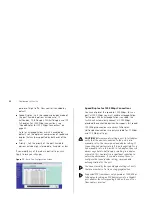
After the Web interface loads in your Web browser, the 
first page that appears is the logon screen. On this 
screen, you need to enter the administration user name 
and password to gain access to the Web interface. 

The logon screen also displays the IP address that the 
Switch is currently using.

Figure 6   

Logon Screen

To log on to the Web interface:

1

In 

Username

, type 

admin

.

2

Leave the 

Password

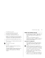
 field blank.

3

Click 

OK

.

Navigating Around the Web Interface

The Web interface has been designed to enable you to 
easily perform advanced configuration tasks and view 
information about the Switch.

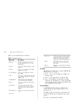
Main Menu

The menu is located on the left side of the Web 
interface. When you click an item on the menu, the 
related screen appears in the main part of the interface.

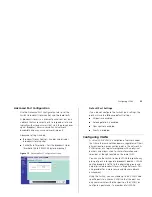
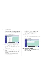
Figure 7   

Switch Screen Layout

Main Menu

Information Screen

Device Mimic


Summary of Contents for 2848 SFP - Baseline Switch Plus

Page 1: ...www 3com com Part No DUA1648 6AAA01 Published January 2006 Baseline Switch 2848 SFP Plus User Guide Installationsanleitung 3C16486 ...

Page 2: ...gree not to remove or deface any portion of any legend provided on any licensed program or documentation contained in or delivered to you in conjunction with this User Guide Unless otherwise indicated 3Com registered trademarks are registered in the United States and may or may not be registered in other countries 3Com 3Com Express 3Com Guardian and the 3Com logo are registered trademarks of 3Com ...

Page 3: ...5 Supplying Power to the Switch 16 Checking for Correct Operation 16 Using SFP Tranceivers 17 Approved SFP Transceivers 17 Inserting an SFP Transceiver 17 Removing an SFP Transceiver 18 Performing Spot Checks 19 3 CONNECTING TO THE WEB INTERFACE Requirements for Accessing the Web Interface 21 Running the Discovery Application 21 Logging On to the Web Interface 23 Navigating Around the Web Interfac...

Page 4: ...41 Restart 41 Configuration 41 Resetting to Factory Defaults 42 Backing Up and Restoring Configuration 42 Upgrade 42 Spanning Tree 43 Support 44 5 TROUBLESHOOTING Forgotten Password 45 Forgotten Static IP Address 45 Solving LED Issues 45 If the Problem Persists 48 A OBTAINING SUPPORT FOR YOUR PRODUCT Register Your Product 49 Purchase Value Added Services 49 Troubleshoot Online 49 Access Software D...

Page 5: ...rks voraus If release notes are shipped with your product and the information there differs from the information in this guide follow the instructions in the release notes Most user guides and release notes are available in Adobe Acrobat Reader Portable Document Format PDF or HTML on the 3Com World Wide Web site www 3com com Conventions Table 1 and Table 2 list conventions that are used throughout...

Page 6: ...ld be directed in the first instance to your network supplier Product Registration You can now register your Baseline Switch on the 3Com Web site to receive up to date information on your product http esupport 3com com Table 2 Text Conventions Convention Description The words enter and type When you see the word enter in this guide you must type something and then press Return or Enter Do not pres...

Page 7: ... which comprised of a RJ 45 port and a Small Form Factor Pluggable SFP transceiver slot on the front panel for easy flexible connection to fiber based Gigabit media Autosensing of MDI MDIX Connections All ports on the Switch can autosense both medium dependent interface MDI and medium dependent interface crossover MDIX connections This allows you to connect network devices to each port using eithe...

Page 8: ...erations 1 RJ 45 10 100 1000 Ports WARNING RJ 45 Ports These are shielded RJ 45 data sockets They cannot be used as standard traditional telephone sockets or to connect the unit to a traditional PBX or public telephone network Only connect RJ 45 data connectors network telephony systems or network telephones to these sockets Either shielded or unshielded data cables with shielded or unshielded jac...

Page 9: ...ou may notice some degradation of network performance 3Com recommends that you use devices that are capable of auto negotiation and that you ensure that auto negotiation is enabled if it is a configurable option 2 Gigabit Combo Ports RJ 45 SFP The Gigabit combo ports RJ 45 Small Form Factor Pluggable SFP ports are numbered 45 to 48 If the link connections on the Gigabit combo ports are active the ...

Page 10: ...cable or fiber is the correct type and is not faulty For fiber connections ensure that the receive RX and transmit TX cable connectors are not swapped If these checks do not identify the cause of the problem it may be that the unit or the device connected to the port is faulty Contact your supplier for further advice Status Meaning Green Module present Off No module present Status Meaning Flashing...

Page 11: ...the unit 9 Recovery Button The recovery button reinitializes the Switch This returns the Switch to the factory default settings if for example you have forgotten the default IP address or forgotten your user name or password CAUTION 3Com recommends that you back up your configuration settings before you recover the Switch otherwise your configuration may be lost Refer to Configuration on page 41 f...

Page 12: ...12 INTRODUCING THE BASELINE SWITCH ...

Page 13: ... C de ce guide WARNHINWEIS Sicherheitsinformationen Bevor Sie Komponenten aus dem Switch entfernen oder dem Switch hinzufuegen oder Instandhaltungsarbeiten verrichten lesen Sie die Sicherheitsanweisungen die in Anhang C Appendix C in diesem Handbuch aufgefuehrt sind ADVERTENCIA Información de Seguridad Antes de instalar o extraer cualquier componente del product o de realizar tareas de mantenimien...

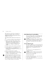
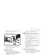
Page 14: ... a ground point If one is not available try to keep in contact with a grounded rack and avoid touching the unit s ports and connectors if possible Static discharge can cause reliability problems in your equipment Rack Mounting or Free Standing The unit can be mounted in a 19 inch equipment rack using the mounting kit or it can be free standing Do not place objects on top of the unit or stack CAUTI...

Page 15: ...Entfernen Sie die selbstklebenden Polster Füße von der Unterseite der Baugruppe falls diese bereits angebracht sind 1 Plazieren Sie die Baugruppe aufrecht auf einer harten ebenen Fläche mit der Vorderseite zu Ihnen 2 Ordnen Sie eine der Halterungen über den Löchern an der Seite der Baugruppe an 3 Stecken Sie zwei der mitgelieferten Schrauben in die Löcher und drehen Sie diese mit einem geeigneten ...

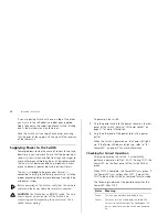
Page 16: ...curely connected CAUTION The Switch has no ON OFF switch The only way to power on and power off the Switch is by connecting and disconnecting the power cord This is called power cycling To power on the Switch 1 Plug the power cord into the power socket on the rear panel of the Switch Refer to 8 Power Socket on page 11 for more information 2 Plug the other end of the power cord into a power outlet ...

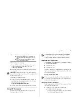
Page 17: ...them from and insert them into any SFP port without having to power down the Switch Approved SFP Transceivers The following list of approved SFP transceivers is correct at the time of publication 3CSFP91 SFP SX 3CSFP92 SFP LX To access the latest list of approved SFP transceivers for the Switch on the 3Com Web site enter this URL into your Internet browser http www 3com com 3Com recommends using 3...

Page 18: ...ly inserted only one way If the transceiver does not click when you insert it remove it turn it over and reinsert it 3 Remove the plastic protective cover if fitted 4 Connect the fiber cable 5 Attach a male duplex LC connector on the network cable into the duplex LC connector on the transceiver 6 Connect the other end of the cable to a device fitted with an appropriate Gigabit Ethernet connection ...

Page 19: ...Com recommends periodically checking the items listed in Table 1 Table 1 Items to Check If you experience any problems operating the Switch refer to Troubleshooting on page 45 Cabling Check that all external cabling connections are secure and that no cables are pulled taut Cooling fan Where possible check that the cooling fan is operating by listening to the unit The fan is fitted near to the fron...

Page 20: ...20 INSTALLING THE SWITCH ...

Page 21: ...eb Interface Running the Discovery Application Logging On to the Web Interface Navigating Around the Web Interface Accessing the Interface Without Using Discovery Requirements for Accessing the Web Interface To connect to the Web interface you need the following The Discovery application which is included on 3Com Baseline Switch 2848 SFP Plus CD ROM that is supplied with your Switch A computer tha...

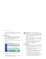
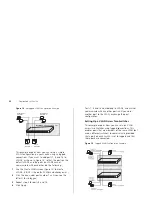
Page 22: ...lcome Screen of Discovery 2 If the computer has multiple network adapters select the adapter that connects the computer to the Switch and then click Next If the computer has only one adapter click Next Discovery searches the network for 3Com devices When detection is complete the Discovered Devices screen displays detected network devices Figure 5 Discovered Devices Screen 3 On the Discovered Devi...

Page 23: ...urrently using Figure 6 Logon Screen To log on to the Web interface 1 In Username type admin 2 Leave the Password field blank 3 Click OK Navigating Around the Web Interface The Web interface has been designed to enable you to easily perform advanced configuration tasks and view information about the Switch Main Menu The menu is located on the left side of the Web interface When you click an item o...

Page 24: ...ry of the Switch s basic settings and versions of current components Password Allows you to change the administrator password IP Setting Allows you to configure the IP address settings of the Switch Port Configuration Allows you to configure the Switch s port settings VLANS Allows you to create VLAN groups add port members and specify how VLAN tagging is used Link Aggregation Allows you to set up ...

Page 25: ...on refer to Automatic IP Configuration on page 29 To determine the IP address that the Switch will assign to itself during auto IP configuration check the sticker on the base of the Switch This sticker contains the MAC address and default IP address of the Switch DHCP Assigned IP Address If you set the IP address mode to DHCP check the DHCP server for the IP address that is assigned to the Switch ...

Page 26: ...26 CONNECTING TO THE WEB INTERFACE ...

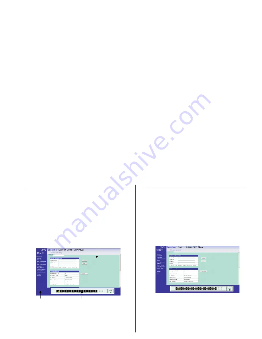
Page 27: ...ion as a basic layer 2 switch you do not need to access the Web interface and configure the Switch You only need to access the Web interface if you want to Set the administration password to the Web interface Assign an IP address to the Switch Configure the Switch s advanced features Upgrade the firmware Viewing Switch Information The Summary screen which automatically loads after you log on to th...

Page 28: ...Settings screen shown in Figure 10 on page 30 Switch Information Shows the serial number total number of ports and the version of the hardware board on the Switch Management Software Information Shows the versions of the loader firmware and the operation code version Changing the Admin Password To prevent unauthorized users from accessing the Web interface and modifying the Switch s settings the i...

Page 29: ...he network to communicate with the Switch you need to assign an IP address to it either by DHCP or by manually assigning a static IP address By default the Switch performs automatic IP configuration and assigns an IP address to itself This is necessary for the Discovery application to be able to connect to the Web interface Automatic IP Configuration When you power on the Switch for the first time...

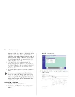
Page 30: ... 3Com recommends using automatic IP configuration only for the initial setup Once you gain access to the console you should assign an IP address to the Switch either by using DHCP or assigning a static IP address to ensure successful communication between the Switch and other network devices Setting the IP Address To set the IP address for the Switch 1 On the menu click IP Settings The IP Settings...

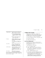
Page 31: ...he Switch regulates the packet flow so that a sending device does not transmit more packets than a receiving device can process If flow control is disabled packets may be dropped under certain IP Address Mode Specify how the Switch will get its IP address Available options include DHCP Select this option if you have a DHCP server on the net work and you want the Switch to automatically obtain an I...

Page 32: ...onegotiation is enabled the Switch will automatically connect at 1000 Mbps provided the connected device also supports this speed 1000 Mbps connections are always full duplex Half duplex connections are only available for 10 Mbps and 100 Mbps settings CAUTION Before manually setting a port to full duplex verify that the device connected to the port is also manually set to the same speed and duplex...

Page 33: ...e following default settings All ports are enabled Autonegotiation is enabled Flow control is enabled Priority is disabled Configuring VLANs A virtual LAN VLAN is a collection of network nodes that share the same collision domain regardless of their physical location or connection point in the network A VLAN serves as a logical workgroup with no physical barriers and allows users to share informat...

Page 34: ...able to access the Web interface If this happens you will need to reset the Switch to factory settings By default all ports belong to VLAN 1 as an untagged member Also newly created VLANs will initially have no ports associated with them Each port will always belong to either VLAN 0 or 1 as an untagged member However they can belong to multiple VLANs as a tagged member Modify VLANs Click the icon ...

Page 35: ... a VLAN ID and the port is a member untagged or tagged of that VLAN the frame is accepted Otherwise the if the port is not a member of that VLAN the frame is discarded When a port receives an untagged frame and the port is an untagged member of a VLAN the frame is accepted and assigned to that VLAN ID Otherwise if the port is not an untagged member of any VLAN the frame is discarded The Switch wil...

Page 36: ...l you see the letter U for Untagged 3 Repeat step 2 for ports 8 and 16 4 Click Apply Ports 7 8 and 16 now belong to VLAN2 and will not communicate with any other ports until you add another port to the VLAN or change the port configuration Setting Up a VLAN Across Two Switches This example explains how you can set up a VLAN across two Switches using tagged connections This enables ports that are m...

Page 37: ...tion and ensures fault recovery Trunking permits the connection of multiple ports to the same remote device to achieve higher network throughput For link aggregation to work the trunks must be configured on both ends of the switches The Switch does not support the Link Aggregation Control Protocol LACP which is specified in IEEE 802 3ad Guidelines for creating Trunks Any of the ports on the Switch...

Page 38: ... trunk settings 1 On the Modify Delete tab modify any of the following settings Name Allows you to label an interface up to characters Flow Control Allows automatic or manual selection of flow control Speed Duplex Allows auto negotiation to be enabled or disabled When autonegotiation is disabled you can force the settings for speed duplex mode and flow control 2 Click Apply To delete a trunk click...

Page 39: ... Rx To reset all packet counts to zero click Clear Counters To view detailed statistics for each port click the port number The statistics page for the port appears as shown in Figure 20 Figure 20 Port Statistics Page Figures on the Statistics page for individual ports are not updated in real time To view the latest statistics for the port click Refresh Monitoring Traffic The Switch allows you to ...

Page 40: ...h traffic Figure 21 Traffic Monitoring Screen To set up traffic monitoring for a port 1 Attach a network analyzer to a port 2 Access the Web interface and then click Port Mirroring on the menu 3 Specify the monitor port and analyzer port from the list Monitor Port This is the port that is to be monitored Analyzer Port This is the port to which the analyzer is attached 4 Click Apply For information...

Page 41: ...ll be lost This function may be of use if you are experiencing problems and you want to re establish your Internet connection Figure 23 Restart Screen Any network users who are currently accessing the Internet will have their access interrupted while the restart takes place and they may need to reboot their computers when the restart has completed and the Switch is operational again Configuration ...

Page 42: ...th the Switch Backing Up and Restoring Configuration To back up the Switch s setting to a configuration file click Backup You will be prompted to download and save a file to disk To reload previously saved configuration 1 Scroll down the page and then click Browse to locate the backup file on your computer 2 Click Restore to copy the configuration back to the Switch For security purposes restoring...

Page 43: ...if you do the software may be corrupted and the Switch may not start up properly afterwards If the Power LED continues to flash after a failed upgrade refer to Troubleshooting on page 45 Spanning Tree This administrative tool supports the configuration of the Switch to forward or block and discard 802 1D spanning tree BPDU packets Spanning tree is a bridge based system for providing fault toleranc...

Page 44: ...ing traffic Figure 26 Spanning Tree Screen Forward Spanning tree BPDU packets received on a port are forwarded to all other ports Block and Discard Spanning tree BPDUs received on a port are dropped The Switch does not forward BPDUs to other ports The Switch does not participate as a bridge node in the spanning tree it can only be configured to forward or block spanning tree BPDUs If the Switch is...

Page 45: ...o Factory Defaults on page 42 for instructions After resetting the Switch log on to the Web interface using the default admin account settings User name admin Password blank no password Forgotten Static IP Address If you forget the static IP address that you assigned to the Switch and you need to access the Web interface use the Discovery application to automatically detect the IP address and conn...

Page 46: ...led and correctly configured The Link Activity LED is lit but the network performance of the Switch is poor The Switch supports full duplex auto negotiation If the connected device does not support auto negotiation ensure it is configured for half duplex operation only If the connected device has auto negotiation disabled or over ridden and is configured as full duplex the Switch will configure th...

Page 47: ...Switch on the network Otherwise you can restore the default settings using the recovery button on the rear panel of the Switch For details on how to use Discovery to detect the Switch on the network refer to Running the Discovery Application on page 21 CAUTION Before recovering the Switch save the Switch s current configuration Recovering the Switch will cause the current configuration to be lost ...

Page 48: ...sists If the problem persists and the unit still does not operate successfully contact your supplier with the following information Product number and serial number printed on a label supplied with the unit A brief description of the fault ...

Page 49: ...ue added services like 3Com ExpressSM and GuardianSM can include 24x7 telephone technical support software upgrades onsite assistance or advance hardware replacement Experienced engineers are available to manage your installation with minimal disruption to your network Expert assessment and implementation services are offered to fill resource gaps and ensure the success of your networking projects...

Page 50: ...contact 3Com for assistance please have the following information ready Product model name part number and serial number Proof of purchase if you have not pre registered your product A list of system hardware and software including revision level Diagnostic error messages Details about recent configuration changes if applicable To send a product directly to 3Com for repair you must first obtain a ...

Page 51: ...a repair authorization number RMA by fax using this number 65 543 6348 Europe Middle East and Africa Telephone Technical Support and Repair From anywhere in these regions call 44 0 1442 435529 From the following countries you may use the numbers shown Austria Belgium Denmark Finland France Germany Hungary Ireland Israel Italy Luxembourg Netherlands Norway Poland Portugal South Africa Spain Sweden ...

Page 52: ...112 AT T 800 998 2112 AT T 800 998 2112 AT T 800 998 2112 AT T 800 998 2112 AT T 800 998 2112 AT T 800 998 2112 AT T 800 998 2112 AT T 800 998 2112 AT T 800 998 2112 AT T 800 998 2112 AT T 800 998 2112 52 55 52 01 00 04 01 800 849CARE 01 800 849 2273 AT T 800 998 2112 AT T 800 998 2112 AT T 800 998 2112 AT T 800 998 2112 AT T 800 998 2112 Puerto Rico Saba Anquila St Kitts Neives St Lucia St Vincen...

Page 53: ...is sions EN50081 1 EN 55022 Class A EN50082 1 IEC 1000 4 2 3 4 6 EN60555 2 Class A EN 60555 3 FCC Part 15 Subpart B Class A Immunity EN 55024 Operating Tempera ture 0 45 C 32 113 F Storage Tempera ture 40 70 C 40 158 F Humidity 0 95 non condensing Standard EN 60068 IEC 68 various parts Width 44 cm 17 3 in Depth 23 8 cm 9 4 in Height 4 4 cm 1 7 in or 1U Weight 3 2 kg 7 05 lb Mounting Free standing ...

Page 54: ...54 APPENDIX B TECHNICAL INFORMATION ...

Page 55: ...n The appliance coupler the connector to the unit and not the wall plug must have a configuration for mating with an EN60320 IEC320 appliance inlet The socket outlet must be near to the unit and easily accessible You can only remove power from the unit by disconnecting the power cord from the outlet This unit operates under SELV Safety Extra Low Voltage conditions according to IEC 60 The condition...

Page 56: ...l n y a pas de connexion de mise à la terre mise à la masse Vous devez raccorder ce groupe à une sortie mise à la terre mise à la masse afin de respecter les normes internationales de sécurité Le coupleur d appareil le connecteur du groupe et non pas la prise murale doit respecter une U S A and Canada The cord set must be UL approved and CSA certified The minimum specifications for the flexible co...

Page 57: ...ectrique Il doit être agréé dans le pays d utilisation AVERTISSEMENT Ports pour fibres optiques sécu rité sur le plan optique Ne regardez jamais le laser tant qu il est sous tension Ne regardez jamais directement le port à fibres optiques et les embouts de câbles à fibres optiques tant qu ils sont sous tension Etats Unis et Canada Le cordon doit avoir reçu l homologation des UL et un certifi cat d...

Page 58: ...ie Netzsteckdose muß in der Nähe des Geräts und leicht zugänglich sein Die Stromversorgung des Geräts kann nur durch Herausziehen des Gerätenetzkabels aus der Netzsteckdose unterbrochen werden Der Betrieb dieses Geräts erfolgt unter den SELV Bedingungen Sicherheitskleinstspannung gemäß IEC 60950 Diese Bedingungen sind nur gegeben wenn auch die an das Gerät angeschlossenen Geräte unter SELV Bedingu...

Page 59: ...lly configure to use the best common speed The order of preference best first is 1000BASE T full duplex 100BASE TX full duplex 100BASE TX half duplex 10BASE T full duplex and 10BASE T half duplex Auto negotiation is defined in the IEEE 802 3 standard for Ethernet and is an operation that takes place in a few milliseconds Auto negotiation must be enabled for the 1000BASE T ports to operate at 1000 ...

Page 60: ...to 1000 Mbps Category 6 Cables One of five grades of Twisted Pair TP cabling defined by the EIA TIA 568 B standard Category 6 can be used in Ethernet 10BASE T Fast Ethernet 100BASE TX and Gigabit Ethernet 1000BASE T networks and can transmit data at speeds of up to 1000 Mbps Client The term used to describe the desktop PC that is connected to your network DHCP Dynamic Host Configuration Protocol T...

Page 61: ...e IEEE Std 802 3 2002 IETF Internet Engineering Task Force An organization responsible for providing engineering solutions for TCP IP networks In the network management area this group is responsible for the development of the SNMP protocol IP Internet Protocol IP is a layer 3 network protocol that is the standard for sending data through a network IP is part of the TCP IP set of protocols that de...

Page 62: ...ess associated with a particular network device Most devices that connect to a LAN have a MAC address assigned to them as they are used to identify other devices in a network MAC addresses are 6 bytes long Network A Network is a collection of computers and other computer equipment that are connected for the purpose of exchanging information or sharing resources Networks vary in size some are withi...

Page 63: ...e that interconnects several LANs to form a single logical LAN that comprises of several LAN segments Switches are similar to bridges in that they connect LANs of a different type however they connect more LANs than a bridge and are generally more sophisticated TCP IP Transmission Control Protocol Internet Protocol This is the name for two of the most well known protocols developed for the interco...

Page 64: ...des that share the same collision domain regardless of their physical location or connection point in the network A VLAN serves as a logical workgroup with no physical barriers and allows users to share information and resources as though located on the same LAN ...

Page 65: ...rient the receiving antenna Relocate the equipment with respect to the receiver Move the equipment away from the receiver Plug the equipment into a different outlet so that equipment and receiver are on different branch circuits If necessary the user should consult the dealer or an experienced radio television technician for additional suggestions The user may find the following booklet prepared b...

Page 66: ......
Page 67: ...ration overview 27 conventions text About This Guide 6 CSA statement 65 D DHCP 60 diagram front panel 8 Discovery 21 dynamic host control protocol 60 E Ethernet 60 F Fast Ethernet 60 FCC statement 65 Feedback about this User Guide 6 firmware upgrading 42 forgotten default IP address 47 password 47 user name 47 front panel diagram 8 full duplex 61 G Gigabit Ethernet 60 Glossary 59 H half duplex 61 ...

Page 68: ...oved supported 17 inserting 17 removing 18 spot checks 19 subnet mask 63 support 44 Switch changing the password 28 positioning 13 restarting 41 switch defined 63 system tools 41 T TCP IP 61 defined 63 technical specifications 53 traffic 63 troubleshooting LED related issues 45 POST failed 17 U upgrading firmware 42 user name default 28 V viewing individual port statistics 39 statisitcs 39 VLANs c...

Reviews: