400
C
HAPTER
25: C
ONFIGURING
DLS
W
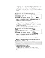
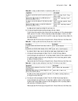
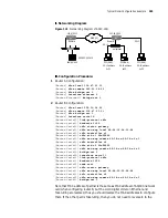
above example, c1 and c2 are the equipment of PU2.0 type, and c3 is the
equipment of PU2.1 type.
Diagnosis and
Troubleshooting of
DLSw Fault
The normal communication of DLSw requires the sound coordination between the
two SNA equipments and two routers operating DLSw, which participate in the
communication. Problem in the co-ordination between any of the two points is
likely to result in failure in connection.
Fault 1: TCP channel can not be created. The status shown is DISCONNECT
when using command display dlsw remote.
Creating TCP channel is the first step for the successful connection of DLSw. If TCP
connection can't be established, the problem lies between the two routers.
Generally, the problem is the configuration of IP address of the router. You can
check if the IP address of remote-peer is accessible by the ping command with the
source address. Also you can use display ip routing-table command to see if there
is any route to the network segment. TCP connection can be created once both
parties have established correct routes.
Fault 2: circuit can not be created correctly. To display dlsw circuits, the
virtual circuit can't attain CONNECTED state.
There are many causes that circuit can't be created. First of all, please make sure
that TCP connection to the opposite end is successfully established. If TCP
connection can be established successfully, while circuit can' t be created, this is
generally caused by the problem in the coordination of the router and SNA
equipment, mainly the problem of SDLC configuration.
Firstly, open the debugging switch of SDLC to observe if the SDLC interface can
receive and send messages successfully. You can use display interface command to
observe the condition of receiving and sending messages on the interface. If the
messages can't be received and sent correctly, it is generally because something is
wrong with the encoding mode of the interface, baud rate or clock configuration.
Generally, this can be solved by modifying the interface configuration parameter
of the router or adjusting the configuration parameter of SDLC equipment.
If the messages can be received and sent correctly, please check if the
configuration PU type is correct. You can use sdlc xid command to configure XID,
changing the setup of PU type.
If the messages can be received and sent correctly, you can check with display dlsw
circuits verbose command to see if the virtual circuit can enter into CIRCUIT_EST
status. If CIRCUIT_EST is not accessible all the time, it suggests that something is
wrong with the coordination between the MAC address and the partner
configured. Generally, this can be solved by modifying configuration parameters
such as sdlc partner.
If circuit can attain CIRCUIT_EST state, but can not attain CONNECTED state, it
suggests that the SDLC configuration of the router and the configuration of SNA
equipment are not matching. Check the configuration of SDLC equipment on
both ends and the configuration of the router to see if the configuration of the
XID of SNA equipment (PU2.1) and the configuration of XID of the router (PU2.0)
are correct. If nothing is wrong with the configuration, check the SDLC line on the
Summary of Contents for 3036
Page 1: ...http www 3com com 3Com Router Configuration Guide Published March 2004 Part No 10014299 ...
Page 4: ...VPN 615 RELIABILITY 665 QOS 681 DIAL UP 721 ...
Page 6: ...2 ABOUT THIS GUIDE ...
Page 7: ...I GETTING STARTED Chapter 1 3Com Router Introduction Chapter 2 3Com Router User Interface ...
Page 8: ...4 ...
Page 16: ...12 CHAPTER 1 3COM ROUTER INTRODUCTION ...
Page 34: ...30 ...
Page 60: ...56 CHAPTER 3 SYSTEM MANAGEMENT ...
Page 98: ...94 CHAPTER 6 DISPLAY AND DEBUGGING TOOLS ...
Page 110: ...106 ...
Page 114: ...110 CHAPTER 8 INTERFACE CONFIGURATION OVERVIEW ...
Page 158: ...154 CHAPTER 10 CONFIGURING WAN INTERFACE ...
Page 168: ...164 ...
Page 188: ...184 CHAPTER 13 CONFIGURING PPPOE CLIENT ...
Page 192: ...188 CHAPTER 14 CONFIGURING SLIP Router ip route static 0 0 0 0 0 0 0 0 10 110 0 1 ...
Page 248: ...244 CHAPTER 16 CONFIGURING LAPB AND X 25 ...
Page 320: ...316 ...
Page 330: ...326 CHAPTER 20 CONFIGURING IP ADDRESS ...
Page 362: ...358 CHAPTER 21 CONFIGURING IP APPLICATION ...
Page 374: ...370 CHAPTER 23 CONFIGURING IP COUNT ...
Page 406: ...402 CHAPTER 25 CONFIGURING DLSW ...
Page 408: ...404 ...
Page 452: ...448 CHAPTER 29 CONFIGURING OSPF ...
Page 482: ...478 CHAPTER 30 CONFIGURING BGP ...
Page 494: ...490 CHAPTER 31 CONFIGURING IP ROUTING POLICY ...
Page 502: ...498 ...
Page 508: ...504 CHAPTER 33 IP MULTICAST ...
Page 514: ...510 CHAPTER 34 CONFIGURING IGMP ...
Page 526: ...522 CHAPTER 36 CONFIGURING PIM SM ...
Page 528: ...524 ...
Page 532: ...528 CHAPTER 37 CONFIGURING TERMINAL ACCESS SECURITY ...
Page 550: ...546 CHAPTER 38 CONFIGURING AAA AND RADIUS PROTOCOL ...
Page 590: ...586 CHAPTER 40 CONFIGURING IPSEC ...
Page 599: ...IX VPN Chapter 42 Configuring VPN Chapter 43 Configuring L2TP Chapter 44 Configuring GRE ...
Page 600: ...596 ...
Page 638: ...634 CHAPTER 43 CONFIGURING L2TP ...
Page 649: ...X RELIABILITY Chapter 45 Configuring a Standby Center Chapter 46 Configuring VRRP ...
Page 650: ...646 ...
Page 666: ...662 ...
Page 670: ...666 CHAPTER 47 QOS OVERVIEW ...
Page 700: ...696 CHAPTER 49 CONGESTION MANAGEMENT ...
Page 706: ...702 CHAPTER 50 CONGESTION AVOIDANCE ...
Page 707: ...XII DIAL UP Chapter 51 Configuring DCC Chapter 52 Configuring Modem ...
Page 708: ...704 ...
Page 762: ...758 CHAPTER 52 CONFIGURING MODEM ...


