background image


3Com Router 3000 ADSL2+ Family 

Installation Guide 


Router 3040 (3C13640) 

Router 3041 (3C13641) 

Router 3040E (3CR13640-75) 

Router 3041E (3CR13641-75) 


www.3Com.com 

Part Number: 10014936 Rev. AA 

March 2006 

Summary of Contents for 3040

Page 1: ...3Com Router 3000 ADSL2 Family Installation Guide Router 3040 3C13640 Router 3041 3C13641 Router 3040E 3CR13640 75 Router 3041E 3CR13641 75 www 3Com com Part Number 10014936 Rev AA March 2006 ...

Page 2: ...ited States government agency then this documentation and the software described herein are provided to you subject to the following All technical data and computer software are commercial in nature and developed solely at private expense Software is delivered as Commercial Computer Software as defined in DFARS 252 227 7014 June 1995 or as a commercial item as defined in FAR 2 101 a and as such is...

Page 3: ...n a Vertical Surface 2 2 2 3 Connecting the Ground Wire 2 3 2 4 Connecting the Power Cord 2 3 2 4 1 AC input power supply 2 3 2 4 2 Connecting the AC input power cord 2 3 2 5 Connecting the Router to a Console Terminal 2 4 2 5 1 Console cable 2 4 2 5 2 Connecting the console cable 2 4 2 6 Connecting the Router to LAN 2 5 2 6 1 Ethernet cable 2 5 2 6 2 Connecting an Ethernet cable 2 5 2 7 Verifying...

Page 4: ...2 Family Installation Guide Table of Contents ii Chapter 4 Troubleshooting 4 1 4 1 Troubleshooting the Power System 4 1 4 2 Troubleshooting the Configuration System 4 1 4 3 Recovering Replacing a Lost Boot ROM Password 4 2 ...

Page 5: ...tion to connect to the central office device through a subscriber line thus providing broadband access to the Internet In this series the Router 3041 provides ISDN backup When the ADSL ADSL2 ADSL2 link fails the ISDN interface can take over to ensure ongoing communications In the downlink direction the Router 3040 provides four 10 100BASE TX layer 2 L2 Ethernet ports which can be isolated via VLAN...

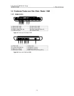
Page 6: ...hernet LED LAN2 4 Ethernet LED LAN1 5 ADSL2 link LED DSL LNK 6 ADSL2 activity LED DSL ACT 7 System LED SYS 8 Power LED PWR Figure 1 1 Front view of the Router 3040 1 Power switch 2 Power socket 3 Console port CONSOLE 4 Ethernet port 1 LAN1 5 Ethernet port 2 LAN2 6 Ethernet port 3 LAN3 7 Ethernet port 4 LAN4 8 ADSL2 over POTS interface ADSL Figure 1 2 Rear view of the Router 3040 ...

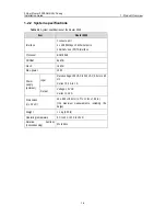
Page 7: ...DSL2 over POTS interface Processor BCM 6348 SDRAM 64 MB Flash 16 MB Max power 10 W Input Rated voltage 100 VAC to 240 VAC 50 Hz to 60 Hz Current 0 5 A to 1 A Power supply external Output Voltage 12 VDC Current 1 25 A Dimensions H x W x D 45 x 300 x 180 mm 1 77 x 11 81 x 7 09 in the maximum measurements including the bulge Weight 1 kg 2 20 lb Operating temperature 0 C to 40 C 32 F to 104 F Relative...

Page 8: ...T OFF means no data is being sent or received Blinking means the interface is sending and or receiving data SYS Blinking means the system is operating normally Steady ON or OFF means the system is improperly operating PWR OFF means no power is being supplied Steady ON means power is being supplied 1 2 4 Interface attributes The interfaces that the 3Com Router 3040 provides are described as follows...

Page 9: ...s auto sensing Full half duplex L2 switching within the scope of the four Ethernet ports 1 2 4 3 ADSL2 over POTS interface Table 1 5 Attributes of the ADSL2 over POTS interface Attribute Description Connector RJ 11 Interface rate 1 Mbps uplink 20 Mbps to 24 Mbps downlink Interface standard ITU T G 992 1 G DMT ITU T G 992 2 G Lite ANSI T1 413 Issue 2 ITU T G 992 3 ITU T G 992 5 Service ADSL2 access...

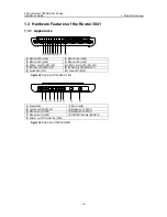
Page 10: ...ink LED DSL LNK 6 ADSL2 activity LED DSL ACT 7 ISDN link LED ISDN LNK 8 ISDN activity LED ISDN ACT 9 System LED SYS 10 Power LED PWR Figure 1 3 Front view of the Router 3041 1 Power switch 2 Power socket 3 Console port CONSOLE 4 Ethernet port 1 LAN1 5 Ethernet port 2 LAN2 6 Ethernet port 3 LAN3 7 Ethernet port 4 LAN4 8 ISDN BRI interface ISDN BRI 9 ADSL2 over POTS interface ADSL Figure 1 4 Rear vi...

Page 11: ... interface 1 ISDN BRI S T interface Processor BCM 6348 SDRAM 64 MB Flash 16 MB Max power 10 W Input Rated voltage 100 VAC to 240 VAC 50 Hz to 60 Hz Current 0 5 A to 1 A Power supply external Output Voltage 12 VDC Current 1 25 A Dimensions H x W x D 45 x 300 x 180 mm 1 77 x 11 81 x 7 09 in the maximum measurements including the bulge Weight 1 kg 2 20 lb Operating temperature 0 C to 40 C 32 F to 104...

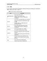
Page 12: ...ne is activated Steady ON means the ADSL ADSL2 ADSL2 line is activated Blinking means the connected two parties are negotiating parameters DSL ACT OFF means no data is being sent or received Blinking means the interface is sending and or receiving data ISDN LNK OFF means the ISDN link is not activated ON means the ISDN link has been activated ISDN ACT OFF means no data is being sent or received on...

Page 13: ...erface and one ADSL2 over POTS interface The following table describes the attributes of the ISDN S T interface Table 1 8 Attributes of the ISDN S T interface Attribute Description Connector RJ 11 Protocol and standard ITU T I 430 Q 921 and Q 931 recommendations Operating mode ISDN dial up ISDN leased line Service ISDN ISDN supplementary services Multi subscriber number Subaddress Backup ...

Page 14: ...ring installation making sure that it has good skin contact z Reserve adequate clearance at the air intake and exhaust vents for ventilation z For power supply use a single phase three line power socket with a neutral point or use a universal PC power socket making sure that the neutral point is well connected to building ground z Make sure the correct voltage is used z Put a lightning arrester at...

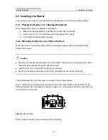
Page 15: ...he four brackets at the bottom of the router Caution z Securely anchor these four mounting screws in the vertical surface If the screws are not properly anchored strain of the network cable connections can pull the router from the wall z Install the router in such a position that the LEDs can be read easily z Securely fix the external power supply unit of the router preventing the power cord from ...

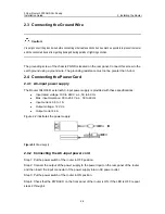
Page 16: ... Router 3040 3041 external AC input power supply is provided with these specifications z Input rated voltage 100 to 240 V a c 50 to 60 Hz z Max input tolerance 90 to 264 V a c 50 to 60 Hz z Input current 0 5 to 1A z Output voltage 12 V d c z Output current 4 A Figure 2 2 illustrates the power supply Figure 2 2 Power supply 2 4 2 Connecting the AC input power cord Step 1 Put the power switch of the...

Page 17: ...5 2 Connecting the console cable Follow these steps to connect the router to a console terminal Step 1 Select a console terminal The console terminal can be either a standard ASCII terminal with an RS 232 serial interface or more commonly a PC Step 2 Connect the console cable Power off the router and the console terminal and then connect the RS 232 serial port on the console terminal to the consol...

Page 18: ...le at both ends of which the wires are crimped in the RJ 45 connectors in different sequence The cable is used for connecting the same type of devices such as PC to PC or PC to router Caution In preparing network cables shielded cables are preferred for the sake of electromagnetic compatibility 2 6 2 Connecting an Ethernet cable Caution Read the mark above the port to be connected carefully before...

Page 19: ... Installing the Router 2 6 2 7 Verifying Installation After you complete installation verify that z The proper power supply is used z The grounding wire of the router is correctly connected z The console cable and the power cord are correctly connected ...

Page 20: ...rt on the router and the DB9 connector to the serial port on the console terminal a PC for example as shown in Figure 3 1 PC Router Console cable Console port Figure 3 1 Local configuration through the console port 3 1 1 2 Setting terminal parameters Follow these steps to set terminal parameters on the console terminal a PC that runs Windows98 for example Step 1 Start the PC and select Start Progr...

Page 21: ... 3 displays Step 3 Select the serial port to be used from the Connect Using dropdown menu The serial port must be the same port connected by the console cable Figure 3 3 Setting the connection port Step 4 Click OK The Port Settings tab shown in Figure 3 4 appears and you can set serial port parameters Set the following parameters Baud rate 9600 Databit 8 Parity check none Stopbit 1 Flow control no...

Page 22: ...g communications parameters Step 6 Click OK The HyperTerminal dialogue box appears Step 7 Select Properties Step 8 In the Properties dialog box select the Settings tab as shown in Figure 3 5 Step 9 Select VT100 or Auto detect in the Emulation dropdown menu Step 10 Click OK Figure 3 5 Setting the terminal type ...

Page 23: ...500000 3Com 3000 Routers Boot ROM V9 00 Copyright C 1997 2003 by 3Com Corp CO LTD Compiled at 17 11 06 Aug 19 2003 Testing memory OK 64M bytes SDRAM 8192k bytes flash memory Hardware Version is MTR 2 0 CPLD Version is CPLD 1 0 Press Ctrl B to enter Boot Menu System is self decompressing OK System is starting Starting at 0x10000 Press Enter The system displays if login authentication is not enabled...

Page 24: ...ot the router Type the correct password and press Enter If no Boot ROM password is configured just press Enter The system accesses the following Boot menu Boot Menu 1 Download application program with XMODEM 2 Download application program with NET 3 Clear configuration 4 Clear application password 5 Start up and ignore configuration 6 Enter debugging environment 7 Boot Rom Operation Menu 8 Do not ...

Page 25: ...et name tn startup script s other o Note You can change the parameter settings behind the colons The 3040 3041 allows you to download programs through both TFTP and FTP z After you set the parameters select 2 to start downloading 3 To clear application password select 4 in the Boot Menu This is used for clearing a superuser password The setting takes effect only once and at a reboot superuser pass...

Page 26: ... option 8 to ignore the version check during software upgrading Note that this option works only once after you select it Then the system resumes version check at reboot 3 2 2 Upgrading Programs through XModem When you upgrade software through XModem you can do that using the console port without having to set up another configuration environment 3 2 2 1 Upgrading an application program Step 1 Ent...

Page 27: ... Send Step 6 After completing downloading the system begins writing data to the Flash and then displays the following information in the terminal interface indicating completion of the downloading Download completed Writing to flash memory Please wait it needs a long time Please wait Writing FLASH Success Please use 9600 bps Press ENTER key to reboot the system Restore the speed of the console ter...

Page 28: ...tion of the Boot ROM program so you can make a second attempt once errors occur 3 2 3 Backing up and Restoring the Extended Segment of the Boot ROM Program 3 2 3 1 Backing up the extended segment of the Boot ROM program to the Flash Follow these steps to back up the extended segment of the Boot ROM Step 1 Enter the Boot menu and then select 7 to enter the Boot ROM operation sub menu Step 2 Select ...

Page 29: ...am You need to purchase and install one by yourself Follow these steps to upgrade an application program through TFTP or FTP 1 Start the TFTP or FTP server Start the TFTP or FTP server on the PC connected to the Ethernet interface on the router and set the path to the file that is to be downloaded For the FTP server you must also set username and password 2 Enter the Boot Menu and select 2 to down...

Page 30: ... following message appears boot device fei unit number 0 processor number 0 host name 8040 file name Q8040 BIN inet on ethernet e 10 110 27 235 host inet h 10 110 27 231 user u 8040 ftp password pw 8040 flags f 0x80 Attached TCP IP interface to fei0 Subnet Mask 0xfffff800 Attaching network interface lo0 done Loading NET download completed read len 04378489 Please wait it needs a long time Writing ...

Page 31: ...d If POWER LED is still OFF after you check against the items listed above contact your agent 4 2 Troubleshooting the Configuration System If the router is operating normally after it is powered on it displays the start up information on the console terminal If the configuration system has faults it displays illegible characters or nothing at all Symptoms 1 Nothing is displayed on the terminal scr...

Page 32: ...owered on Solution Make sure you have set on your terminal HyperTerminal Baud rate 9600 Databit 8 Parity check none Stopbit 1 Flow control none Terminal emulation VT100 Reconfigure the parameters if their values are different 4 3 Recovering Replacing a Lost Boot ROM Password If the Boot ROM password of the router is lost contact the local agent of 3Com for help ...

Reviews: