


3Com Router Module Guide
Chapter 3 Multifunctional Interface Modules
3-13
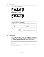
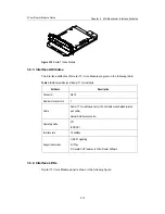
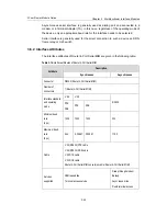
Figure 3-17
Router T1 Voice Module panel
Description of the LEDs on Router T1 Voice Module panel is given in the following
table.
Table 3-7
Description of the LEDs on Router T1Voice Module panel
LED Description
LINK
OFF means no link is present; ON means a link is present.
ACTIVE
OFF means no data is being transmitted or received; blinking means data is being
received or/and transmitted.
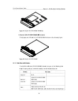
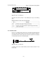
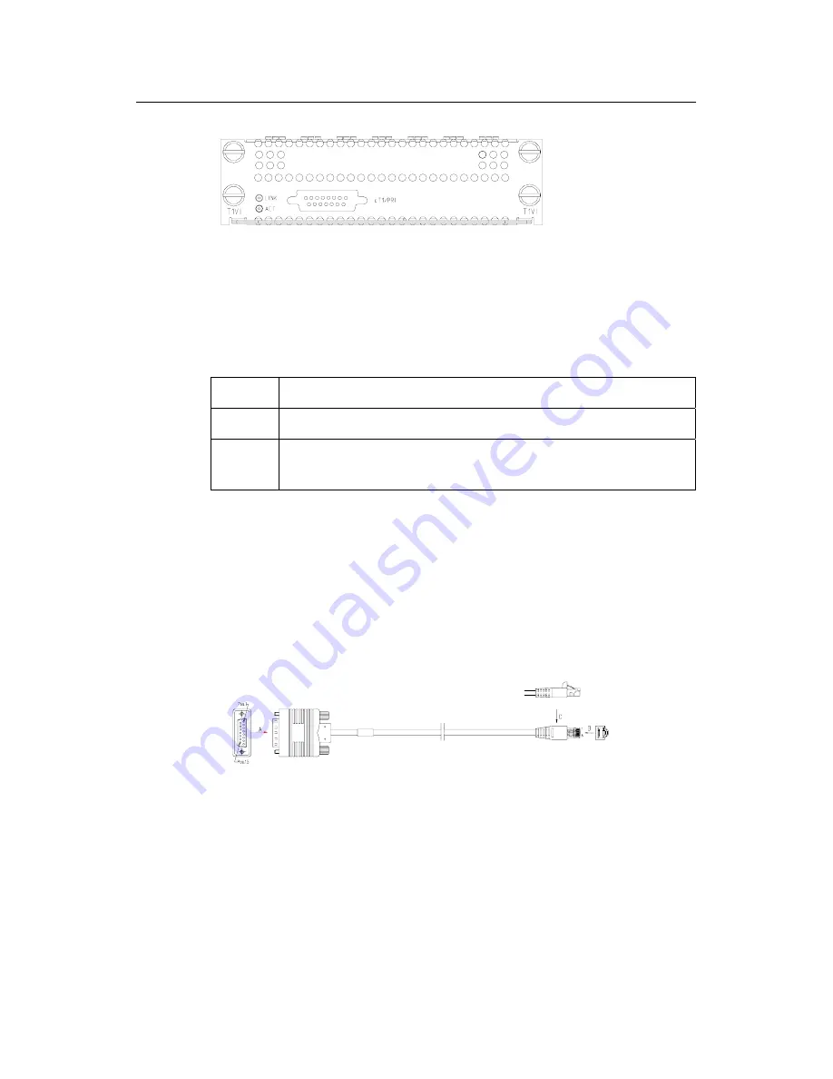
3.3.5 Interface Cable
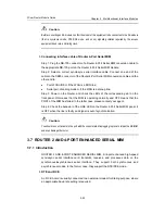
Router T1 Voice Module interface cables are 100-ohm balanced shielded twisted pairs.
At one end of each cable is a DB-15 male connector for the connection to a Router T1
Voice Module module, and at the other end is an RJ-45 connector for the connection
to the voice device, as shown in the following figure:
Figure 3-18
Router T1 Voice Module cable
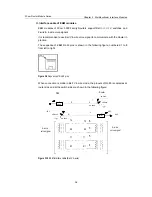
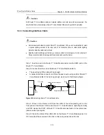
In addition, you may use a network interface connector to extend a Router T1 Voice
Module cable.


