background image

3Com Router Module Guide 

Chapter 2  Smart Interface Cards


2-22 

LP/AL 

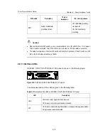
ON means the interface is in a loopback. 

Blinking means an AIS, LFA, or RAI alarm signal is present. 

OFF means no loopback or alarm is present.   

Note:  

AIS = Alarm indication signal; LFA = loss of frame alignment; RAI = Remote alarm indication   


2.5.5  Interface Cable


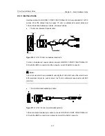
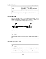
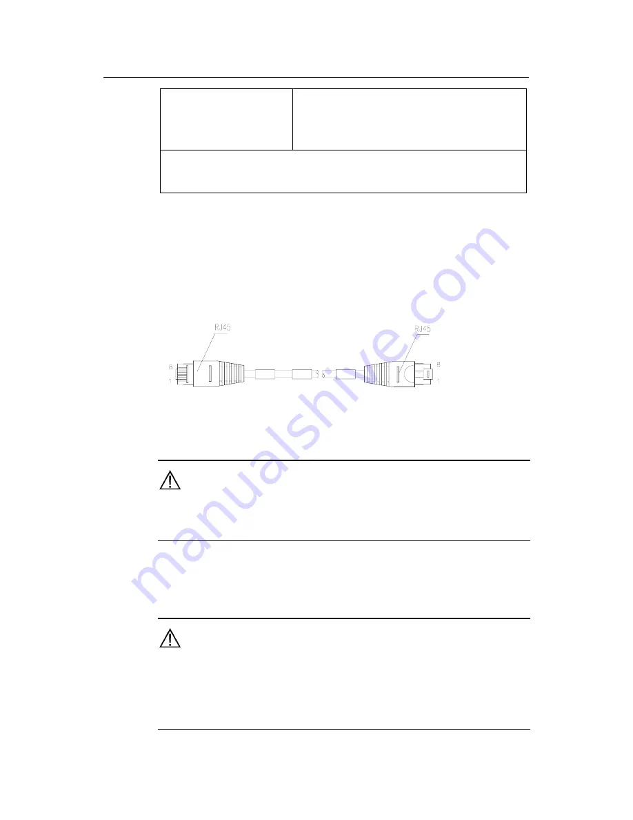
ROUTER 1-PORT FRACTIONAL T1 SIC interface cable is 100-ohm standard 
shielded network cable that has RJ-45 connectors at both ends. The following figure 
illustrates a ROUTER 1-PORT FRACTIONAL T1 SIC interface cable: 


Figure 2-22


T1 cable


  Caution:


Relevant cables are included in the standard shipment package of ROUTER 1-PORT FRACTIONAL T1 
SIC. 


2.5.6  Connecting Interface Cable 


  Caution:


z


You should connect a cable to the port with the correct mark. Misplugging is prone to impair the 
SIC/MIM and even damage the router.


z


When using T1 cable outdoors, you are recommended to install a special lightning arrester on the 
input end of the cable so as to avoid lightning more effectively.


Summary of Contents for 3C13886 - Router OC-3 ATM SML Flexible Interface...

Page 1: ...i 3Com Router Modules Installation Guide http www 3com com Part No DIA1372 8AAA01 Published September 2005...

Page 2: ...3 2 2 1 Introduction 2 3 2 2 2 Appearance 2 4 2 2 3 Interface Attributes 2 5 2 2 4 Interface LEDs 2 6 2 2 5 Interface Cable 2 6 2 2 6 Connecting Interface Cable 2 8 2 3 ROUTER 2 PORT ISDN S T SIC and...

Page 3: ...ble 2 28 2 7 6 Connecting Interface Cable 2 29 Chapter 3 Multifunctional Interface Modules Router 5000 3 1 3 1 Router 2 Port FXS FXO E M MIM Modules Router 4 Port 4FXS 4FXO 4E M MIM Modules 3 1 3 1 1...

Page 4: ...ENHANCED SERIAL MIM 3 25 3 7 1 Introduction 3 25 3 7 2 Interface Attributes 3 26 3 7 3 Interface LEDs 3 27 3 7 4 Interface Cable 3 28 3 7 5 Connecting the Interface Cable 3 31 3 8 Router 2 and 4 Port...

Page 5: ...erface LEDs 3 53 3 13 5 Troubleshooting 3 54 3 14 ROUTER 4 PORT E1 IMA MIM 3 55 3 14 1 Introduction 3 55 3 14 2 Appearance of the Interface Card 3 55 3 14 3 Interface Attributes 3 55 3 14 4 Panels and...

Page 6: ...Optical Fiber 3 65 4 1 12 Connecting the Interface Optical Fiber 3 65 4 2 ROUTER 1 PORT 10 100 1000 FIC 3 65 4 2 1 Introduction 3 65 4 2 2 Interface Attributes 3 65 4 2 3 Panel and Interface LEDs 3 6...

Page 7: ...3 66 4 8 5 Connecting the Interface Cable 3 66 4 9 ROUTER 1 PORT T3 ATM FIC 3 66 4 9 1 Introduction 3 66 4 9 2 Interface Attributes 3 66 4 9 3 Panel and Interface LEDs 3 66 4 9 4 Interface Cable 3 66...

Page 8: ...4 PORT FXO FIC 3 66 4 15 1 Introduction 3 66 4 15 2 Interface Attributes 3 66 4 15 3 Panel and Interface LEDs 3 66 4 15 4 Interface Cable 3 66 4 15 5 Connecting the Interface Cable 3 66 4 16 ROUTER 1...

Page 9: ...18 z Router 1 Port Fractional T1 SIC 3C13720 z Router 1 Port Fractional E1 SIC 3C13722 z Router 1 Port Analog Modem SIC 3C13724 z Router 1 port FXS SIC card 3C13725 z Router 2 port FXS SIC card 3C1372...

Page 10: ...C13860 z Router 2 Port 10 100 FIC 3C13861 z Router 1 Port 100FX SM FIC 3C13862 z Router 4 Port Enhanced Serial FIC 3C13863 z Router 8 Port Enhanced Serial FIC 3C13864 z Router 4 Port CE1 PRI FIC 3C138...

Page 11: ...and MIMs Before implementing any of the following operations wear an anti static wrist strap and ESD preventive glove and make sure that the power of the Router has been turned off and the power cord...

Page 12: ...ll a SIC Step 1 Place the rear panel of the Router towards you Step 2 Turn off the power switch of the Router and unplug the power cord Step 3 Take out the SIC and align its remote edge with the edge...

Page 13: ...sis 1 5 2 Installing Removing MIM I Tools required z Flat blade screwdriver z ESD preventive wrist strap and ESD preventive glove II Installing MIM Follow these steps to install a MIM Step 1 Place the...

Page 14: ...panel of the Router Step 4 Loosen the captive screws at both sides of the MIM Step 5 Pull the MIM towards you until it is completely separated from the bottom of the router 1 6 Troubleshooting 3Com 5...

Page 15: ...in abnormal state check that z Proper interface cable is used z The LEDs on the panel of SIC MIM are displaying normally see the section introducing the SIC MIM for its LED status and description z Th...

Page 16: ...1 1 Interface Attributes The interface attributes of Router 1 Port 10 100 SIC are given in the following table Table 2 1 Interface attributes of Router 1 Port 10 100 SIC Attribute Router 1 Port 10 100...

Page 17: ...of twisted pair cable crimped in the RJ 45 connectors at both ends are different It can be used to connect two terminal devices such as PCs and Routers You can such kind of cables by yourself if nece...

Page 18: ...cal loopback and remote loopback facilitating fault test and location I Synchronous and asynchronous In different operating modes a synchronous asynchronous serial interface supports different signal...

Page 19: ...nerally the Router is used as a DTE device To make sure that the device is a DTE or DCE refer to the manual shipped with this device In addition the following table may also help you to identify the t...

Page 20: ...ing table Table 2 5 Interface attributes of ROUTER 1 PORT SERIAL SIC Description Attribute Synchronous Asynchronous Connector type DB50 Number of connectors 1 Cable type V 24 RS232 DTE cable V 24 RS23...

Page 21: ...g table Table 2 6 Description of the LEDs on ROUTER 1 PORT SERIAL SIC panel LINK OFF means no link is present ON means a link is present ACT OFF means no data is being transmitted or received blinking...

Page 22: ...a connector whose type varies by the network device or line type to be connected Caution The four types of cables listed above are optional which must be selected while purchasing the ROUTER 1 PORT S...

Page 23: ...ug synchronous asynchronous serial interface cables when the Router has power Otherwise it is likely to damage the equipment and ports If the SIC has been properly installed follow these steps to conn...

Page 24: ...heck the line 2 3 ROUTER 2 PORT ISDN S T SIC and ROUTER 2 PORT ISDN U SIC 2 3 1 Introduction 1 2 port ISDN BRI S T interface cards ROUTER 2 PORT ISDN S T SIC serve to transmit receive and handle one a...

Page 25: ...ISDN U SIC Attribute Description Connector type RJ 45 ROUTER 2 PORT ISDN S T SIC RJ 45 ROUTER 2 PORT ISDN U SIC compatible with RJ11 Number of connectors 1 2 Cable type Telephone cable with ferrite co...

Page 26: ...on is being conducted ACT OFF means deactivation Blinking means activating process ON means active status ON OFF means the power to the SIC is disconnected caused by the failure of power supply to the...

Page 27: ...the line use NT1 for conversion The connecting procedure is to insert one end of the telephone cable with ferrite core into the BRI S T interface of ROUTER 2 PORT ISDN S T SIC and the other end into t...

Page 28: ...lt test and location It is possible to use the card for multiple purposes through different configurations Following are the differences between SIC EPRI and 1 port Fractional E1 interface card ROUTER...

Page 29: ...DB15 to RJ 45 Coaxial connector network interface connector and 75 ohm to 120 ohm adapter Operating mode E1 cE1 ISDN PRI supported by SIC EPRI only FE1 supported by ROUTER 1 PORT FRACTIONAL E1 SIC onl...

Page 30: ...settings of the internal DIP switch of SIC ERRI ROUTER 1 PORT FRACTIONAL E1 SIC DIP switch Description 75 ohm impedance 120 ohm impedance 1BIT ON OFF 2BIT ON OFF 3BIT ON OFF 4BIT ON OFF 5BIT Switch f...

Page 31: ...tion of internal DIP switch is that all the 8 positions of the BIT switch are ON that is the E1 interface impedance is 75 ohm 2 4 5 Interface LEDs ROUTER 1 PORT FRACTIONAL E1 SIC panel is shown in the...

Page 32: ...ure 2 16 E1 G 703 75 ohm non balanced coaxial cable 75 ohm non balanced coaxial cable connects ROUTER 1 PORT FRACTIONAL E1 SIC with the DB15 connector and the network end with the BNC connector Note A...

Page 33: ...recommended to install a special lightning arrester on the input end of the cable in order to avoid lightning more effectively If the SIC has been properly installed follow these steps to connect the...

Page 34: ...le is a 120 ohm balanced twisted pair cable z Directly connect the RJ 45 connector of the cable to the RJ 45 port of the remote equipment if there is no need to extend the E1 cable or z Connect the RJ...

Page 35: ...z ISDN PRI function z Remote loopback and local loopback facilitating the effective and flexible debugging It is possible to use the card for multiple purposes through different configurations Follow...

Page 36: ...FT1 supported by ROUTER 1 PORT FRACTIONAL T1 SIC only Supported service Backup Terminal access ISDN supported by SIC TPRI ony 2 5 4 Interface LEDs ROUTER 1 PORT FRACTIONAL T1 SIC panel is shown in th...

Page 37: ...twork cable that has RJ 45 connectors at both ends The following figure illustrates a ROUTER 1 PORT FRACTIONAL T1 SIC interface cable Figure 2 22 T1 cable Caution Relevant cables are included in the s...

Page 38: ...SIC panel ON means the link is connected and OFF means the link is not connected In the latter case check the line 2 6 ROUTER 1 PORT ANALOG MODEM SIC 2 6 1 Introduction 1 2 port analog modem interfac...

Page 39: ...hone cable with ferrite core Maximum speed 56kbps Supported standard ITU T V 90 V 34 33 6 kbps V FC V 32 bis V 32 V 22 bis V 22A B V 23 V 21 Bell 212A a Bell 103 Supported service Modem dial up 2 6 4...

Page 40: ...ing arrester on the input end of the telephone line in order to avoid the lightning effects more efficiently If the SIC has been properly installed follow these steps to connect the cable Step 1 Inser...

Page 41: ...provide ordinary analog telephone and fax access and also can connect AT0 loop trunks of exchanges z FXO SIC cards are loop trunk cards that provide access of common subscriber lines of exchanges Cau...

Page 42: ...ctors 1 Router 1 Port FXS FXO SIC 2 Router 2 Port FXS FXO SIC Interface standard Subscriber circuit interface Router 1 or 2 Port FXS SIC compliant with ITU Q 512 Loop trunk interface SIC 1FXO SIC 2FXO...

Page 43: ...SIC panels LED Description LINK OFF means the link is idle ON means the link is being occupied for call connection ACT OFF means the link is idle ON means the link is being occupied for communication...

Page 44: ...e To ensure the compatibility of the Router users should connect the end with the ferrite core to the Router If the SIC is properly installed follow these steps to connect the cable Step 1 Connect the...

Page 45: ...analog trunk interface module Router 2 or 4 Port FXO MIM serves to access and handle 2 4 channels of common user lines of telephone exchange 2 4 port voice E M analog trunk interface module Router 2...

Page 46: ...ter 4 Port FXS FXO E M 3 1 3 Interface Attributes The interface attributes of FXS FXO E M modules are given in the following table Table 3 1 Interface attributes of 2FXS 2FXO 2E M and 4FXS 4FXO 4E M a...

Page 47: ...face Router 2 or 4 Port E M E M interface supporting Bell type I II III V and support 2 wire and 4 wire ITU K 20 compliant overcurrent and overvoltage protection Dial up mode DTMF Dual Tone Multi Freq...

Page 48: ...uter 2 Port FXS FXO and Router 4 Port FXS FXO are telephone cables with ferrite core and both ends of which are RJ11 connectors Cables for Router 2 and 4 Port E M need to be selected according to the...

Page 49: ...ctice The sequence of E M RJ 45 pins is shown in the following figure numbered 1 to 8 from left to right Figure 3 9 Sequence of RJ 45 pins When connection is made in Bell V 4 wire mode the pinouts of...

Page 50: ...2 Port FXS FXO and Router 4 Port FXS FXO modules are magnetic loop lines with a ferrite core at one end To ensure EMC of the Router connect the end with ferrite core to the Router z Because it is hard...

Page 51: ...tep 1 Plug one end of the cable into the RJ 45 port on Router 2 Port FXS FXO E M Step 2 Connect the other end of the cable to z Telephone set fax or AT0 loop trunk of telephone exchange if you have in...

Page 52: ...ibutes of Router E1 Voice Module Attribute Description Connector DB15 Number of connectors 1 Operating mode 1 E1 2 CE1 3 ISDN PRI Interface rate 2 048Mbps Cable E1 120 ohm balanced twisted pair cable...

Page 53: ...d Blinking means there is data being transmitted or received 3 2 5 Interface Cable Router E1 Voice Module interface cables are G 703 compliant 120 ohm balanced twisted pair cables At one end of the ca...

Page 54: ...Cable Caution z Some measures are taken to protect Router E1 Voice Module Still you are recommended to install a special lightning arrester at the input end of its connection cable to obtain better l...

Page 55: ...3 Power on the Router and check the LEDs of the corresponding slot on the front panel ON means Router E1 Voice Module is operating normally and OFF means the POST of Router E1 Voice Module has failed...

Page 56: ...ce attributes of Router T1 Voice Module Attribute Description Connector DB15 Number of connectors 1 Cable Router T1 Voice Module cable 100 ohm balanced shielded twisted pair cable Network interface co...

Page 57: ...no data is being transmitted or received blinking means data is being received or and transmitted 3 3 5 Interface Cable Router T1 Voice Module interface cables are 100 ohm balanced shielded twisted p...

Page 58: ...end of a Router T1 Voice Module cable into the DB15 port on the Router T1 Voice Module Step 2 Connect the other end of the Router T1 Voice Module cable to z The peer device if the cable is long enoug...

Page 59: ...g and implements the VPN with encryption features and then the NDEC will complete the task of encryption 3 4 2 Appearance The appearance of NDEC module is shown in the following figure Figure 3 20 NDE...

Page 60: ...mal blinking 1 second ON and 1 second OFF The module is operating normally Steady ON The software initialization has failed and the service cannot be run normally ACT Fast blinking The module is in th...

Page 61: ...ACT SPEED and DENY are ON it is likely the problem of the NDEC or the Router RUN LED keeps ON after several times of blinking if module initialization fails 4 Symptom 4 RUN LED is fast blinking all th...

Page 62: ...transmission segment over the category 5 twisted pair cable z Operation at 100 Mbps and 10 Mbps autosensing z Full duplex and half duplex with the former in common use 3 5 2 Interface Attributes The...

Page 63: ...cards are category 5 twisted pairs with RJ 45 connectors Pins 1 and 2 of the interface are used for transmitting data and pins 3 and 6 are used for receiving data Figure 3 23 Ethernet cable II Making...

Page 64: ...and check the behavior of the LINK LED on the panel ON means that a link is present and OFF means that no link is present In the latter case check the line status Caution Before you connect a port rea...

Page 65: ...E and DCE Synchronous serial interfaces support both DTE and DCE operating modes Given two directly connected devices if one operates in the DTE mode the other will operate in the DCE mode The DCE dev...

Page 66: ...Router 4 Port Serial MIM are given in the following table Table 3 14 Interface attributes of Router 4 Port Serial MIM Description Attribute Synchronous Asynchronous Connector DB100 Router 4 Port Seria...

Page 67: ...means data is being received or and transmitted 3 6 4 Interface Cable I Router 4 Port Serial MIM interface cable Router 4 Port Serial MIM provides a 1 to 4 conversion cable Router 4 Port Serial MIM co...

Page 68: ...ange Series Routers Cable Manual Caution Router 4 Port Serial MIM conversion cable is the required by Router 4 Port Serial MIM module while the four sync async serial interface cables are optional You...

Page 69: ...er on the Router and check the LEDs of the corresponding slot on the front panel ON means that the MIM is operating normally and OFF means that the POST of the MIM has failed In the latter case please...

Page 70: ...ons and baud rates In addition the maximum signal transmission segment depends not only on the specified baud rate but also on the selected cable The following table shows how the cable type baud rate...

Page 71: ...ard and operating mode DTE DCE DTE DCE RS232 Min baud rate bps 1200 1200 300 Max baud rate bps 64 k 4 096 M 2 048 M 115 2 Cable V 24 RS232 DTE cable V 24 RS232 DCE cable V 35 DTE cable V 35 DCE cable...

Page 72: ...cables with DB 28 connectors Before connecting a card identify the line properties and then select the proper interface cable from the following ten cable options z V 24 RS232 DTE cable DB 25 plug at...

Page 73: ...ctor to connect the router but the connector at the network end varies with the type of the to be connected network z V 24 DTE cable Figure 3 28 V24 DTE cable z V 24 DCE cable Figure 3 29 V 24 DCE cab...

Page 74: ...apter 3 Multifunctional Interface Modules 3 30 Figure 3 32 X 21 DTE cable z X 21 DCE cable Figure 3 33 X 21 DCE cable z RS449 DTE cable Figure 3 34 RS449 DTE cable z RS449 DCE cable Figure 3 35 RS449...

Page 75: ...ce Cable Caution Do not plug or unplug interface cables into or from the MIM card to prevent the device or ports from being impaired Before connecting an MIM card identify the type of the equipment to...

Page 76: ...port channelized E1 PRI interface module transmits receives and processes E1 data traffic In addition you can use the card for other purposes such as CE1 access and the ISDN PRI function II The modul...

Page 77: ...rted by Router 2 and 4 Port CE1 PRI MIM FE1 only supported by Services supported 1 Backup 2 Terminal access service 3 ISDN PRI only supported by Router 2 and 4 Port CE1 PRI MIM 3 8 3 Interface LEDs Th...

Page 78: ...bles and 120 ohm balanced twisted pair cables z 75 ohm unbalanced coaxial cable Figure 3 40 E1 75 ohm unbalanced coaxial cable Note You can select a pair of coaxial connectors with a BNC receptacle at...

Page 79: ...provided II Conversion cable for 4 port module 4 port modules provide two types of 1 to 4 conversion cables 120 ohm 4 port module conversion cable and 75 ohm 4 port module conversion cable At one end...

Page 80: ...rsion cable Figure 3 43 75 ohm 4 port module conversion cable Caution Both 75 ohm 4 port module 1 and 120 ohm 4 port module conversion cables are required for 4 port module modules while E1 cable is o...

Page 81: ...2 port 4 port DIP switch S1 S1 S3 S4 S5 E1 interface Interface 0 Interface 0 Interface 1 Interface 2 Interface 3 By default all the DIP switches for Router 2 and 4 Port CE1 PRI MIM and modules are set...

Page 82: ...n switch OFF RxShield is grounded via capacitance ON RxShield is grounded directly Caution It is recommended to select the DIP switch of Router 2 and 4 Port CE1 PRI MIM and modules in this way when co...

Page 83: ...cable and set the DIP switches module correctly Step 2 Plug the DB 15 connector of the cable into the port on the module Step 3 Connect the other end of the cable to the network device 1 When using 7...

Page 84: ...the POST of the MIM has failed In the latter case please contact your agent Step 5 Check the behavior of the LINK LED on the module panel It is OFF when fault has occurred on the link and signal is ou...

Page 85: ...r 4 Port ISDN S T MIM Module 3 9 1 Introduction 4 port ISDN BRI interface module Router 4 Port ISDN S T MIM serves to transmit receive and handle four channels of data streams on the ISDN BRI S T inte...

Page 86: ...port on 1 2 3 4 5 6 7 8 Figure 3 47 Default setting of DIP switch for Router 4 Port ISDN S T MIM module Table 3 24 Configuration of DIP switches for Router 4 Port ISDN S T MIM module DIP switch Descri...

Page 87: ...on is going on Green lamp on the right OFF means channel B2 is idle ON means channel B2 is occupied and data communication is going on 3 9 5 Interface Cable Interface cables of Router 4 Port ISDN S T...

Page 88: ...MIM has failed In the latter case please contact your agent 3 10 Router 2 Port CT1 PRI MIM 3 10 1 Introduction I Router 2 Port CT1 PRI MIMmodule 1 2 4 port channelized T1 PRI interface module serves...

Page 89: ...2 Terminal access service 3 ISDN PRI Router 2 Port CT1 PRI MIMmodule 3 10 3 Interface LEDs The panel is similar to that of the MIM and they differ only in silk screen Figure 3 50 2T1 2T1 F panel Tabl...

Page 90: ...nnect two network cables Caution Both T1 cable and network interface connector are optional accessories You should order them together with the module Otherwise they will not be provided 3 10 5 Connec...

Page 91: ...and signal is Off 3 11 ROUTER 1 PORT ADSL OVER POTS MIM 3 11 1 Introduction ROUTER 1 PORT ADSL OVER POTS MIM the 1 2 port ADSL over PSTN interface card allows a LAN subscriber to connect to the digit...

Page 92: ...Interface standard ITU T 992 1 G DMT ITU T 992 2 G Lite ANSI T1 413 Issue 2 Interface rate In ADSL full rate mode ITU T 992 1 G DMT ANSI T1 413 8160 kbps downlink rate 896 kbps uplink rate Cable and t...

Page 93: ...package of the ROUTER 1 PORT ADSL OVER POTS MIM includes the regular telephone cable s You can separately order an external splitter as needed 3 11 5 Connecting the Interface Cable In G Lite mode no s...

Page 94: ...P backbone or the Internet to enjoy services such as high speed data communication and video on demand VoD ADSL transmits data in the high frequency band above 26 kHz Therefore it can provide services...

Page 95: ...line 3 12 3 Panel and Interface LED The following figure illustrates the ROUTER 2 PORT ADSL OVER POTS MIM panel Figure 3 55 ROUTER 2 PORT ADSL OVER POTS MIM panel The following table describes the LED...

Page 96: ...the splitter Step 2 Connect the telephone to the phone port on the splitter with another telephone cable Step 3 Connect the external ADSL port on the splitter to the PSTN with a third telephone cable...

Page 97: ...ncryption Accelerator MIM is shown as below Figure 3 57 ROUTER NDEC2 ENCRYPTION ACCELERATOR MIM 3 13 3 Interface Attributes Table 3 32 Router NDEC2 Encryption Accelerator MIM features Feature Descript...

Page 98: ...ower supply of the module or abnormal operation of CPLD Complex Programmable Logic Device In these circumstances contact our agents for support 2 Symptom 2 The ACTIVE LED stays off when powering on th...

Page 99: ...nks and the remote end multiplexes these low speed E1 links to one single cell flow This technology is cost effective and flexible for application and mainly used in network applications that transmit...

Page 100: ...eristic impedance 75 ohm 120 ohm Max transmission distance 500 m 1640 4 in 150 m 492 1 in Operating mode ATM E1 standalone link IMA binding mode Service AAL5 Protocol PPPoA PPPoEoA IPoA IPoEoA Transmi...

Page 101: ...ble can be connected with four twisted pairs 3 14 6 Connection of the Interface Cable Perform the following procedure to connect the RT ROUTER 4 PORT E1 IMA MIM interface cable 1 Choose an appropriate...

Page 102: ...erface card provides four T1 interfaces that support the IMA technology The network application of the two cards is similar to the IMA 8E1 IMA 4E1 interface card 3 15 2 Appearance of the Interface Car...

Page 103: ...of the ROUTER 4 PORT T1 IMA MIM interface cards Figure 3 63 Front panel of the IMA 4T1 interface card The LEDs on the front panel of the ROUTER 4 PORT T1 IMA MIM panel as described in the following ta...

Page 104: ...qual to 128 when working in CE3 mode Note E3 represents the tertiary group rate of E system in the TDM system that is 34 368Mbps An E3 channel can be channelized into 16 E1 lines through the demultipl...

Page 105: ...data is being transmitted or received blinking means data is being received or and transmitted 3 16 4 Interface Cable The external interface provided by a Router 1 Port CE3 MIM module is two SMB socke...

Page 106: ...tter case please contact your agent Step 4 Check the behavior of the LINK LED on the Router 1 Port CE3 MIM panel It is OFF when the line is faulty and signal is out of synchronization In this case che...

Page 107: ...erface rate 44 736 Mbps Interface cable type T3 cable 75 ohm coaxial cable Operating mode T3 CT3 Services supported T3 leased line 3 17 3 Interface LEDs Router 1 Port CT3 MIM panel is shown in the fol...

Page 108: ...M the 1 port 10Base T 100Base TX 1000Base T Ethernet electrical interface card is used for router to LAN communication The cards support z 100 meters 328 1 ft of transmission segment over the category...

Page 109: ...is present ACT OFF means no data is being transmitted or received Blinking means data is being transmitted and or received 3 18 3 Interface Cable ROUTER 1 PORT 10 100 1000 MIM uses both crossover and...

Page 110: ...3Com Router Module Guide Chapter 3 Multifunctional Interface Modules 3 66...

Page 111: ...erface Attributes 4 11 4 2 3 Panel and Interface LEDs 4 11 4 2 4 Interface Cable 4 12 4 2 5 Connecting the Interface Cable 4 12 4 3 ROUTER 4 PORT 8 PORT ENHANCED SERIAL FIC 4 13 4 3 1 Introduction 4 1...

Page 112: ...ntroduction 4 35 4 9 2 Interface Attributes 4 36 4 9 3 Panel and Interface LEDs 4 36 4 9 4 Interface Cable 4 37 4 9 5 Connecting the Interface Cable 4 37 4 10 ROUTER 1 PORT OC 3 ATM MM FIC ROUTER 1 PO...

Page 113: ...tion 4 51 4 15 2 Interface Attributes 4 51 4 15 3 Panel and Interface LEDs 4 52 4 15 4 Interface Cable 4 53 4 15 5 Connecting the Interface Cable 4 53 4 16 ROUTER 1 PORT E1 VOICE FIC 4 54 4 16 1 Intro...

Page 114: ...able z Operation at 100 Mbps and 10 Mbps autosensing z Full duplex and half duplex with the former in common use 4 1 3 Interface Attributes The following table describes the interface attributes of th...

Page 115: ...y 5 twisted pairs with RJ 45 connectors Pins 1 and 2 of the interface are used for transmitting data and pins 3 and 6 are used for receiving data Figure 4 2 Ethernet cable II Making Ethernet cables Yo...

Page 116: ...t through cable for a HUB or LAN switch use a crossover cable Step 2 Power on the router and check the on the FIC FE panel ON means that a link is present and OFF means that no link is present In the...

Page 117: ...ize there are two types of multi mode optical fibers 62 5 m and 50 m the transmission media accepted by the ISO IEC 11801 standard 4 1 9 Interface Attributes The following table describes the interfac...

Page 118: ...and ON means an Rx link is present ACTIVE OFF means no data is being transmitted or received on the interface and blinking means data is being transmitted and or received 4 1 11 Interface Optical Fib...

Page 119: ...of optical fibers are optional You need to select fibers when purchasing an Router 1 Port 100FX MM FIC 100FX SM FIC otherwise they are not provided 4 1 12 Connecting the Interface Optical Fiber Cautio...

Page 120: ...n segment over the category 5 twisted pair cable z Operation at 1000Mbps 100Mbps and 10Mbps auto sensing z Half duplex full duplex autonegotiation 4 2 2 Interface Attributes The following table descri...

Page 121: ...or received Blinking means data is being transmitted and or received 4 2 4 Interface Cable ROUTER 1 PORT 10 100 1000 FIC uses both crossover and straight through cables for connection Figure 4 7 Ethe...

Page 122: ...fied rate The router normally works as a DTE To identify whether the equipment connected to the router is DTE or DCE refer to the manual shipped with the equipment II Speed and transmission segment of...

Page 123: ...terface Attributes The following table describes the interface attributes of the ROUTER 4 PORT ENHANCED SERIAL Table 4 8 Interface attributes of the ROUTER 4 PORT 8 PORT ENHANCED SERIAL Description At...

Page 124: ...e 2 Terminal access service 1 Dialup through modem 2 Backup 3 Asynchronous leased line 4 Terminal access service 4 3 3 Panel and Interface LEDs The following figures show the ROUTER 4 8 PORT ENHANCED...

Page 125: ...line properties and then select the proper interface cable from the following ten cable options z V 24 RS232 DTE cable DB 25 plug at the network end z V 24 RS232 DCE cable DB 25 receptacle at the net...

Page 126: ...le Guide Chapter 4 4 17 z V 24 DCE cable Figure 4 11 V 24 DCE cable z V 35 DTE cable Figure 4 12 V 35 DTE cable z V 35 DCE cable Figure 4 13 V 35 DCE cable z X 21 DTE cable Figure 4 14 X 21 DTE cable...

Page 127: ...Module Guide Chapter 4 4 18 Figure 4 15 X 21 DCE cable z RS449 DTE cable Figure 4 16 RS449 DTE cable z RS449 DCE cable Figure 4 17 RS449 DCE cable z RS530 DTE cable Figure 4 18 RS530 DTE cable z RS53...

Page 128: ...e and line clock Step 1 Identify type of the interface to be connected and then choose the correct synchronous asynchronous serial interface cable Step 2 Plug the DB 28 connector of the cable to the c...

Page 129: ...describes the interface attributes of the FIC E1 and FIC E1 F cards Table 4 10 Interface attributes of the FIC E1 and FIC E1 F cards Description Attribute ROUTER 4 PORT CE1 PRI FIC Connector DB 25 Nu...

Page 130: ...is being transmitted or received on the interface blinking means data is being transmitted and or received 4 4 4 Interface Cable I Interface cable of the ROUTER 4 PORT CE1 PRI FIC Interface cables fo...

Page 131: ...connector with an RJ 45 receptacle at each end to connect the cable to another 120 ohm balanced twisted pair cable In addition you are available with 75 ohm to 120 ohm adapters Note E1 cable coaxial...

Page 132: ...except that the 75 ohm 4E1 adapter cable uses eight coaxial cables but the 120 ohm 4E1 adapter cable uses four twisted pair cables Figure 4 23 120 ohm 4E1 adapter cable Figure 4 24 75 ohm 4E1 adapter...

Page 133: ...he device If outdoor cabling is involved consider to install a special lightning arrester at the input end of the interface cable for better lightning protection I Connecting the interface cable of th...

Page 134: ...wisted pair cable do the following z If no cable extension is needed directly connect the RJ 45 connector of the cable to the RJ 45 port on the device z If cable extension is needed connect the RJ 45...

Page 135: ...E1 cable Step 4 Connect the E1 cable to another device by reference to the previous subsection Step 5 Power on the router and check the behavior of the LINK LED on the card panel OFF means fault occu...

Page 136: ...s FT1 only supported by the cards Supported service Backup Leased line ISDN PRI only supported by the cards 4 5 3 Panel and Interface LEDs The following figure illustrates the panel Figure 4 27 ROUTER...

Page 137: ...provided only when ordered 4 5 5 Connecting the Interface Cable Caution Before you connect a port read its label carefully a wrong connection can cause damages to the interface card and even the devic...

Page 138: ...ugh Figure 4 29 Extending a T1 cable Step 3 Power on the router and check the behavior of the LINK LED on the card panel OFF means fault occurs on the line Check the line status 4 6 ROUTER 1 PORT CE3...

Page 139: ...table describes the LEDs on the card panel Table 4 16 LEDs on the ROUTER 1 PORT CE3 FIC panel LED Description LINK OFF means no link is present ON means a link is present ACT OFF means no data is bei...

Page 140: ...lightning arrester at the input end of the E3 T3 cable for better protection Step 1 Connect the SMB connector of an E3 T3 cable to the Tx port on the ROUTER 1 PORT CE3 FIC and the other end to the Rx...

Page 141: ...emultiplex and T12 means T1 to T2 multiplex or T2 to T1 demultiplex T23 and T12 discussed here represent the demultiplex process 4 7 2 Interface Attributes The following table describes the interface...

Page 142: ...T E3 ATM FIC 4 8 1 Introduction 8 8 ROUTER 1 PORT E3 ATM FIC the 1 port 34Mbps ATM E3 interface card provides these functions z Two ATM cell mapping modes ATM direct mapping ADM and physical layer con...

Page 143: ...1 PORT E3 ATM FIC panel Figure 4 33 8 8 ROUTER 1 PORT E3 ATM FIC panel The following table describes the LEDs on the 8 8 ROUTER 1 PORT E3 ATM FIC panel Table 4 20 LEDs on the 8 8 ROUTER 1 PORT E3 ATM...

Page 144: ...e input end of the E3 T3 cable for better protection Step 1 Connect the SMB connector of an E3 T3 cable to the Tx port on the 8 8 ROUTER 1 PORT E3 ATM FIC and another end to the Rx port on another dev...

Page 145: ...some key services 4 9 2 Interface Attributes The following table describes the interface attributes of the ROUTER 1 PORT T3 ATM FIC Table 4 21 Interface attributes of the ROUTER 1 PORT T3 ATM FIC Att...

Page 146: ...nd 8 8 ROUTER 1 PORT E3 ATM FIC cards use the same type of cables for connection which are called E3 T3 cables in this manual 4 9 5 Connecting the Interface Cable Caution By design the ROUTER 1 PORT T...

Page 147: ...OC 3 ATM SML FIC They provide the following functions z Two frame formats SDH STM 1 and SONET OC 3 z Scrambling in data transmission z Line clock when working as DTE interface and internal clock when...

Page 148: ...Transmitter LD LED LD Optical transmitter power Min 15dBm Max 8dBm Min 15dBm Max 8dBm Min 5dBm Max 0dBm Receiver sensitivity Min 28dBm Max 8dBm Min 30dBm Max 14dBm Min 34dBm Max 10dBm Central wavelen...

Page 149: ...received 4 10 4 Interface Optical Fiber The ROUTER 1 PORT OC 3 ATM MM FIC uses multi mode optical fiber and the ROUTER 1 PORT OC 3 ATM SM FIC ROUTER 1 PORT OC 3 ATM SML FIC uses single mode optical f...

Page 150: ...IP backbone or the Internet to enjoy services such as high speed data communication and video on demand VoD ADSL transmits data in the high frequency band above 26 kHz Therefore it can provide service...

Page 151: ...over the telephone cable depending on the line quality Supported service ADSL over the regular telephone line 4 11 3 Panel and Interface LED The following figure illustrates the ROUTER 1 PORT ADSL FIC...

Page 152: ...and simply connect the phone set in parallel with the router at the cable distribution box Full rate mode requires a splitter Follow these steps to connect the cables Step 1 Plug one end of a telepho...

Page 153: ...This technology is common on a PDH network over which ATM cells are transmitted 4 12 2 Interface Attributes The following table describes the interface attributes Table 4 27 Interface attributes of th...

Page 154: ...ER 4 PORT E1 IMA FIC card provides four E1 ports and adopts a 120 ohm or a 75 ohm 4E1 conversion cable The two types of cables look similar Both of them have a DB 68 connector at one end for connectin...

Page 155: ...he interface type of the device to be connected z If the interface impedance of the device to be connected is 75 ohm use a 75 ohm 4E1 8E1 conversion cable z If the interface impedance of the device to...

Page 156: ...r eight T1 interfaces that support the IMA technology Their network application is similar to that of the ROUTER 4 PORT E1 IMA FIC card 4 13 2 Interface Attributes The following table describes the in...

Page 157: ...or eight T1 ports and uses the 4T1 conversion cable for connection At one end of the cable is a DB 68 connector for connecting the router and at the other end are four or eight RJ 45 connectors for co...

Page 158: ...Table 4 31 Interface attributes of the ROUTER 1 PORT OC3 POS FIC Attribute ROUTER 1 PORT OC3 POS FIC Connector SFP LC Interface standard SONET OC 3 SDH STM 1 Number of interfaces 1 Interface rate 155...

Page 159: ...s optical fibers with LC type connectors see Error Reference source not found 4 14 5 Connecting the Interface Optical Fiber Step 1 Insert the SFP card into its corresponding slot Step 2 Locate the Rx...

Page 160: ...T FXS 4 PORT FXO FIC make sure your router has access to an IP network or some other WAN 4 15 2 Interface Attributes The following table describes the interface attributes of the ROUTER 2 PORT FXS 2 P...

Page 161: ...following figure illustrates the 2 Port FXO panel Figure 4 49 2 Port FXO panel The following figure illustrates the 4 PORT FXS FIC panel Figure 4 50 4 PORT FXS FIC panel The following figure illustrat...

Page 162: ...ludes the regular telephone cables 4 15 5 Connecting the Interface Cable Caution If outdoor cabling is involved consider to install a special lightning arrester at the input end of the interface cable...

Page 163: ...gnals 4 16 2 Interface Attributes The following table describes the ROUTER 1 PORT E1 VOICE FIC interface attributes Table 4 35 Interface attributes of the ROUTER 1 PORT E1 VOICE FIC Attribute Descript...

Page 164: ...smitted or received on the interface and blinking means data is being transmitted and or received 4 16 4 Interface Cable ROUTER 1 PORT E1 VOICE FIC cables are G 703 compliant 120 ohm balanced twisted...

Page 165: ...htning protection Before you connect a port read its label carefully a wrong connection can cause damages to the interface card and even the device Step 1 Insert the DB 15 connector of the cable into...

Page 166: ...means fault occurs on the line Check it for the cause 4 17 ROUTER 1 PORT T1 VOICE FIC 4 17 1 Introduction ROUTER 1 PORT T1 VOICE FIC the 1 port T1 voice interface card is intended for handling dense...

Page 167: ...8 LEDs on the ROUTER 1 PORT T1 VOICE FIC panel LED Description LINK OFF means no link is present ON means a link is present ACTIVE OFF means no data is being transmitted or received on the interface a...

Page 168: ...face card and even the device Step 1 Insert one end of the T1VI cable into the DB 15 port on the ROUTER 1 PORT T1 VOICE FIC Step 2 Connect the other end of the cable to another device directly or afte...

Page 169: ...f your router can implement VPN with encryption provided by the ROUTER NDEC2 ENCRYPTION ACCELERATOR FIC in addition to IP packet forwarding 4 18 2 Interface Features The following table describes the...

Page 170: ...reading the LED behaviors Incorrect LED behaviors Reason Action to take STATUS LED remains OFF at router startup The card or some hardware parts on the card are not supplied with power properly 1 Chec...

Page 171: ...3Com Router Module Guide Chapter 4 4 62...

Reviews: