background image

20

Connecting Hubs Using 10BASE-2

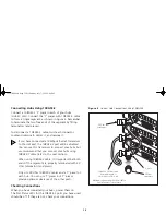
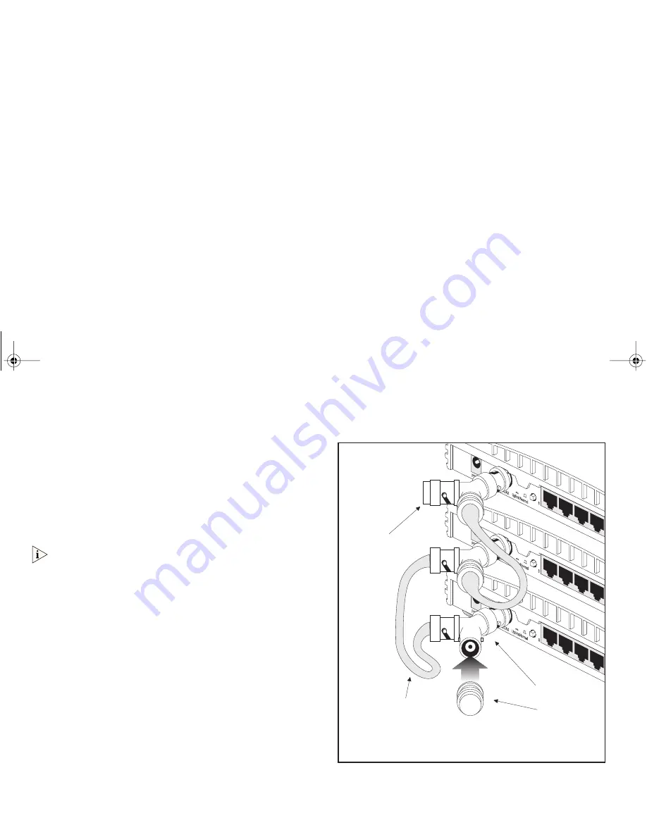
Connect a 10BASE-2 ‘Y’ piece to each of your hubs 
(Hub 8C only). Connect the ‘Y’ pieces with 10BASE-2 cable 
to form a single segment, as shown in Figure 7. Remember 
to terminate the two free ends of the segment by fitting 
terminators (end pieces).

To disconnect a 10BASE-2 cable, twist each connector 
counter-clockwise to unlock it, and remove it.

When using 10BASE-2 cable, it is important that both 
ends of the segment are properly terminated with 
50 Ohm terminators (end pieces).

Only use 50 Ohm 10BASE-2 cables and a ‘Y’ piece for 
each hub. You can use ‘T’ pieces but ‘Y’ pieces 
provide optimum clearance of the other ports.

Checking Connections

When you have connected your hubs, power them on. 
The Port Status LEDs for the 10BASE-2 ports you have used 
should be off. If they are not, check your connections.

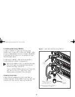
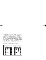
Figure 7   

Correct Hub Connections Using 10BASE-2

50 Ohm

terminator

10BASE-2 50 Ohm cable.

Minimum length of

each cable is 0.5m (1.6ft)

Maximum segment length is 185m (607ft)

(from terminator to terminator)

‘Y’ piece

50 Ohm

terminator

3C16700.book  Page 20  Wednesday, July 7, 1999  5:46 PM

Summary of Contents for 3C16792 - OfficeConnect Dual Speed Switch 16

Page 1: ...OfficeConnect Ethernet Hub 4 4C 8 8C User Guide 3C16704A 3C16703A 3C16700A 3C16701A 3C16700 book Page i Wednesday July 7 1999 5 46 PM ...

Page 2: ...wing All technical data and computer software are commercial in nature and developed solely at private expense Software is delivered as Commercial Computer Software as defined in DFARS 252 227 7014 June 1995 or as a commercial item as defined in FAR 2 101 a and as such is provided with only such rights as are provided in 3Com s standard commercial license for the Software Technical data is provide...

Page 3: ... Connections 14 Spot Checks 14 Problem Solving for the Hub 4 and 4C 15 The OfficeConnect Ethernet Hub 8 and 8C 17 Ethernet Hub 8 and 8C Front 17 Ethernet Hub 8 and 8C Rear 18 Connecting Workstations and Other Equipment to Your Hub 19 Connecting OfficeConnect Ethernet Hubs Together 19 Connecting Hubs Using 10BASE 2 20 Checking Connections 20 Connecting Hubs Using 10BASE T 21 Checking Connections 21...

Page 4: ...ervices 30 World Wide Web Site 30 3Com Knowledgebase Web Services 30 Support from Your Network Supplier 31 Support from 3Com 31 Returning Products for Repair 34 3Com Corporation Limited Warranty 35 Electromagnetic Compatibility 38 3C16700 book Page 4 Wednesday July 7 1999 5 46 PM ...

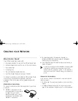
Page 5: ... guide describes how to use the OfficeConnect hubs The hubs have similar features and so this user guide contains general and specific information When referring to all products this guide uses the term OfficeConnect hub A single OfficeConnect hub allows you to create a small network with up to four or eight workstations as shown in Figure 1 If you need to connect more workstations simply use the ...

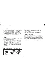
Page 6: ...a range of easy to install network adapter cards which provide your workstations with 10BASE T connections 2 An operating system for example Netware or Windows 95 98 with network support configured running on your workstations 3 One straight through TP cable for every workstation as shown in Figure 2 In order to comply with the 10BASE T standard ports designed for workstation connections have been...

Page 7: ... You can use T pieces but Y pieces provide optimal clearance of the other ports Two 10BASE 2 50 Ohm terminators end pieces Figure 2 Some of the 10BASE 2 Equipment You May Need 10BASE T If you have additional hubs you want to connect using 10BASE T you need One straight through TP cable for each extra hub Twisted Pair TP Cables To connect your workstations and hubs you must use straight through TP ...

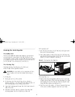
Page 8: ...nting downwards 3 Align the fastening pieces over the slots found on each side of the unit 4 Push the clip down gently to secure it ensuring the fastening pieces snap into the slots on the unit To fit another unit 1 Rest the second unit on top of the clip and align it with the front of the unit below 2 Press down gently on the unit to secure it onto the clip ensuring the fastening pieces fit into ...

Page 9: ...he template at the back of this guide to mark the position of the holes Fix the screws into the wall leaving their heads 3mm 0 12in clear of the wall surface Remove any connections to the hub and locate it over the screw heads When in line gently push the hub on to the wall and move it downwards to secure When making connections be careful not to push the hub up and off the wall CAUTION Only wall ...

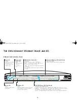
Page 10: ...ork Utilization LEDs Hub 4C only green yellow orange Indicates how much your network is being used 10BASE T Port Status LEDs green yellow green yellow off Indicates the status of each 10BASE T port The link between the port and the next piece of network equipment is OK The port has partitioned due to a fault on that segment Nothing is connected to the port or the link has failed AUI COAX Status LE...

Page 11: ...C only Allows 10Mbps transceivers of different media types to be connected to the hub Connecting a transceiver automatically disables the 10BASE 2 port Uplink Normal switch Affects the operation of port 4 For correct usage refer to Connecting Hubs Using 10BASE T on page 14 Four 10BASE T RJ 45 ports Use 10BASE T cable with RJ 45 connectors You can connect the OfficeConnect hub to any workstation or...

Page 12: ...s so you can start using your network immediately When you need more ports simply add more OfficeConnect hubs Connecting Transceivers to the AUI Port You can connect a 10Mbps Ethernet transceiver to your hub Hub 4C only using a standard AUI cable Connect one end of the cable to the transceiver and the other end to the AUI port on the hub s rear panel This automatically disables the 10BASE 2 port a...

Page 13: ... next section When using 10BASE 2 cable it is important that both ends of the segment are properly terminated with 50 Ohm terminators end pieces Only use 50 Ohm 10BASE 2 cables and a Y piece for each hub You can use T pieces but Y pieces provide optimum clearance of the other ports Checking Connections When you have connected your hubs power them on The Port Status LEDs for the 10BASE 2 ports you ...

Page 14: ...used should be green If they are not check your connections If the 10BASE 2 port is not used and is not terminated and the AUI port is not being used if applicable the LED should be yellow showing that it has partitioned This is correct operation Spot Checks At frequent intervals visually check that The Alert LED is not lit this is the best way to find out if there are problems with your network C...

Page 15: ...t Status LED will be yellow Examine your connections and remove the loop Each piece of equipment needs only one connection to your OfficeConnect hub Port Status LED yellow for a 10BASE T port It is likely that there is a loop in your network which has caused this port to partition Examine your connections and remove the loop Each piece of equipment needs only one connection to your OfficeConnect h...

Page 16: ... switch is set to Normal out Also check that the equipment being connected to the hub is powered on and operating correctly Refer to Figure 6 below to compare the wiring of a straight through and a crossover cable Figure 6 Straight through Cable Crossover Cable Pins 4 5 7 and 8 are not used Straight through Crossover Pins 4 5 7 and 8 are not used TxD TxD RxD RxD 1 2 3 6 1 2 3 6 TxD TxD RxD RxD TxD...

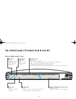
Page 17: ... a port Collision LED yellow Flashes each time a collision is detected on the network Collisions are part of normal network operation Network Utilization LEDs Hub 8C only green yellow orange Indicates how much your network is being used Port Status LEDs green yellow green yellow off Indicates the status of each port The link between the port and the next piece of network equipment is OK The port h...

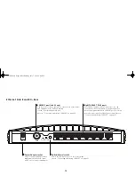
Page 18: ...Connecting Hubs Using 10BASE 2 on page 20 Uplink Normal switch Affects the operation of port 8 For correct usage refer to Connecting Hubs Using 10BASE T on page 21 Eight 10BASE T RJ 45 ports Use 10BASE T cable with RJ 45 connectors You can connect the OfficeConnect hub to any workstation or piece of equipment that has a 10BASE T port Port 8 can be used to link to another OfficeConnect hub Refer to...

Page 19: ...ct the cable push the connector s latch in and remove it If you are using port 8 to connect to a workstation using a straight through TP cable ensure the Uplink Normal switch is set to Normal out The hub detects all port connections so you can start using your network immediately When you need more ports simply add more OfficeConnect hubs Connecting OfficeConnect Ethernet Hubs Together You can inc...

Page 20: ...roperly terminated with 50 Ohm terminators end pieces Only use 50 Ohm 10BASE 2 cables and a Y piece for each hub You can use T pieces but Y pieces provide optimum clearance of the other ports Checking Connections When you have connected your hubs power them on The Port Status LEDs for the 10BASE 2 ports you have used should be off If they are not check your connections Figure 7 Correct Hub Connect...

Page 21: ...t Status LEDs for the 10BASE T ports you have used should be green If they are not check your connections If the 10BASE 2 port is not used and is not terminated the LED should be yellow showing that it has partitioned This is correct operation Spot Checks At frequent intervals visually check that The Alert LED is not lit this is the best way to find out if there are problems with your network Case...

Page 22: ...port has partitioned due to a loop in your network in which case the corresponding Port Status LED will be yellow Examine your connections and remove the loop Each piece of equipment needs only one connection to your OfficeConnect hub Port Status LED yellow for a 10BASE T port It is likely that there is a loop in your network which has caused this port to partition Examine your connections and rem...

Page 23: ...mal switch is set to Normal out Also check that the equipment being connected to the hub is powered on and operating correctly Refer to Figure 9 below to compare the wiring of a straight through and a crossover cable Figure 9 Straight through Cable Crossover Cable 1 Normal port Pin Pin Uplink port Rx Rx Tx Tx Rx Rx Tx Tx 2 3 4 5 6 7 8 1 2 3 4 5 6 7 8 1 Normal port Pin Pin Normal port Rx Rx Tx Tx R...

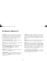
Page 24: ...e than one path Your hub detects this and partitions isolates one of its ports to break the loop A segment is the length of Ethernet cable connected to a port whether this cable is 10BASE T 10BASE 2 or other type When you join equipment together with 10BASE 2 cable via single speed hubs the entire cable forms a single segment Packets are the units of information your workstations and other equipme...

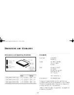
Page 25: ...nscreened cables category 3 or category 5 complies with the Class A requirements Refer to Electromagnetic Compatibility on page 38 for conditions of operation Power Weight OfficeConnect Ethernet Hub 4 4 VA 14 BThU hr 500g 1 1 lb OfficeConnect Ethernet Hub 4C 12 VA 40 BThU hr 550g 1 2 lb OfficeConnect Ethernet Hub 8 11 VA 38 BThU hr 500g 1 1 lb OfficeConnect Ethernet Hub 8C 12 VA 40 BThU hr 550g 1 ...

Page 26: ...ds Improving our environmental record on a continual basis End Of Life Statement 3Com processes allow for the recovery reclamation and safe disposal of all end of life electronic components Regulated Materials Statement 3Com products do not contain any hazardous or ozone depleting material Environmental Statement about the Documentation The documentation for this product is printed on paper that c...

Page 27: ...sible You can only remove power from the unit by disconnecting the power cord from the outlet This unit operates under SELV Safety Extra Low Voltage conditions according to IEC 950 The conditions are only maintained if the equipment to which it is connected also operates under SELV conditions There are no user replaceable fuses or user serviceable parts inside the hub If you have a physical proble...

Page 28: ... durch Herausziehen des Gerätenetzkabels aus der Netzsteckdose unterbrochen werden Der Betrieb dieses Geräts erfolgt unter den SELV Bedingungen Sicherheitskleinstspannung gemäß IEC 950 Diese Bedingungen sind nur gegeben wenn auch die an das Gerät angeschlossenen Geräte unter SELV Bedingungen betrieben werden Es sind keine von dem Benutzer zu ersetzende oder zu wartende Teile in dem Gerät vorhanden...

Page 29: ...l appareil hors circuit qu en débranchant son cordon électrique au niveau de cette prise L appareil fonctionne à une tension extrêmement basse de sécurité qui est conforme à la norme CEI 950 Ces conditions ne sont maintenues que si l équipement auquel il est raccordé fonctionne dans les mêmes conditions Il n y a pas de parties remplaceables par les utilisateurs ou entretenues par les utilisateurs ...

Page 30: ...latest networking information on the 3Com Corporation World Wide Web site enter this URL into your Internet browser http www 3com com This service provides access to online support information such as technical documentation and software as well as support options that range from technical education to maintenance and professional services 3Com Knowledgebase Web Services This interactive tool cont...

Page 31: ...t configuration changes if applicable If you are unable to contact your network supplier see the following section on how to contact 3Com Support from 3Com If you are unable to obtain assistance from the 3Com online technical resources or from your network supplier 3Com offers technical telephone support services To find out more about your support options call the 3Com technical telephone support...

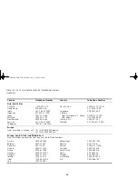
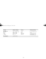
Page 32: ...161 463 00798 611 2230 0 2 3455 6455 0080 611 261 001 800 611 2000 Europe From anywhere in Europe call 31 0 30 6029900 phone 31 0 30 6029999 fax Europe South Africa and Middle East From the following countries you may use the toll free numbers Austria Belgium Denmark Finland France Germany Hungary Ireland Israel Italy 0800 297468 0800 71429 800 17309 0800 113153 0800 917959 0800 1821502 00800 1281...

Page 33: ...0 13 3266 1230 020 0645 98012 2127 Mexico Peru Puerto Rico Venezuela 01 800 CARE 01 800 2273 AT T 800 666 5065 800 666 5065 AT T 800 666 5065 North America 1 800 876 3266 Country Telephone Number Country Telephone Number 3C16700 book Page 33 Wednesday July 7 1999 5 46 PM ...

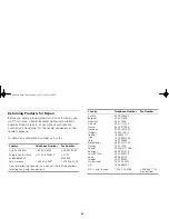
Page 34: ... America 1 408 326 2927 1 408 326 3355 From the following countries you may call the toll free numbers select option 2 and then option 2 Austria Belgium Denmark Finland France Germany Hungary Ireland Israel Italy Netherlands Norway Poland Portugal South Africa Spain Sweden Switzerland U K 0800 297468 0800 71429 800 17309 0800 113153 0800 917959 0800 1821502 00800 12813 1800553117 1800 9453794 1678...

Page 35: ...applications program and associated reference materials 3Com makes no warranty or representation that its software products will meet Customer s requirements or work in combination with any hardware or applications software products provided by third parties that the operation of the software products will be uninterrupted or error free or that all defects in the software products will be correcte...

Page 36: ...ort 3Com com index htm and provide your date of purchase product number and serial number 3Com reserves the right to modify or cancel this telephone support offering at any time without advance notice This offer is not available where prohibited or restricted by law 3Com s Web and Bulletin Board Service are available at no charge and provide software and firmware upgrades a bug list and technical ...

Page 37: ...anties are not allowed to be excluded in their entirety they will be limited to the duration of the applicable written warranty This warranty gives you specific legal rights which may vary depending on local law GOVERNING LAW This Limited Warranty shall be governed by the laws of the State of California U S A excluding its conflicts of laws principles and excluding the United Nations Convention on...

Page 38: ...by one or more of the following measures Reorient the receiving antenna Relocate the equipment with respect to the receiver Move the equipment away from the receiver Plug the equipment into a different outlet so that equipment and receiver are on different branch circuits Consult the dealer or an experienced radio television technician for help CSA STATEMENT This Class B digital apparatus meets al...

Page 39: ...39 Wall mounting screw hole guide 150 mm 5 9 in 3C16700 book Page 39 Wednesday July 7 1999 5 46 PM ...

Page 40: ...Part No DUA 1670 0AAA04 Published June 1999 40 3C16700 book Page 40 Wednesday July 7 1999 5 46 PM ...

Reviews: