118
C
HAPTER
12: P
OWER
M
ANAGEMENT
AND
C
ONTROL
Monitoring Power
Usage using the
Web Interface
The Switch keeps statistics on the power usage of each port. To view the
Power Usage for a port:
1
Log into the Web interface.
2
From the
Device View
, select
Physical Interface > Power > Detail
. The
PoE
Detail
screen will be displayed.
3
Select the port you wish to examine from the drop-down list. The
following information will be displayed:
■
Power Mode or Profile Name
— displays Guaranteed, Not Guaranteed
or the name of the profile selected.
■
State
— displays
Enabled or Disabled if the port is not delivering
power
, or
Active
if the port is currently delivering power. Displays fault
information if the port is not supplying power due to limits of power
budget or another fault.
■
Average Power
— displays the average power that has been supplied
to the device since the meter was last reset. If a device had been
switched off for part of the time, it will register a lower average.
■
Peak Power
— displays the most power supplied to the device since
the meter was last reset.
■
Current Power
— displays the power currently being supplied to the
device.
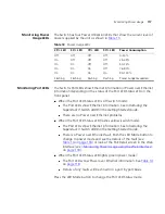
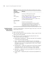
Table 14
Port Status and Port Packet LEDs (Power over Ethernet information)
LED Status
Meaning
Port Status LED
Off
No Power over Ethernet device is present.
Green
Power is being supplied from this port.
Flashing Green
The power budget for Switch or port has been exceeded.
See
“Planning Power Budgets”
on
page 114
.
Yellow
Power over Ethernet error. No power is supplied. Check
your Power over Ethernet device.
Port Packet LED
Off
The port is functioning correctly
Yellow
The port has failed internal test. The port is unable to
supply power, but may still function correctly as an
unpowered Ethernet port. Power cycle the switch. If the
problem persists contact your hardware supplier.
Summary of Contents for 3C17205-US - Corp SUPERSTACK 3 SWITCH 4400...
Page 8: ...GLOSSARY INDEX...
Page 14: ...14...
Page 26: ...26 CHAPTER 1 SWITCH FEATURES OVERVIEW...
Page 44: ...44 CHAPTER 3 USING MULTICAST FILTERING...
Page 55: ...How STP Works 55 Figure 13 STP configurations...
Page 58: ...58 CHAPTER 4 USING RESILIENCE FEATURES...
Page 84: ...84 CHAPTER 7 STATUS MONITORING AND STATISTICS...
Page 92: ...92 CHAPTER 8 SETTING UP VIRTUAL LANS...
Page 98: ...98 CHAPTER 9 USING WEBCACHE SUPPORT...
Page 120: ...120 CHAPTER 12 POWER MANAGEMENT AND CONTROL...
Page 122: ...122...
Page 126: ...126 APPENDIX A CONFIGURATION RULES...
Page 134: ...134 APPENDIX B NETWORK CONFIGURATION EXAMPLES...
Page 150: ...150 GLOSSARY...


