background image

44

C

HAPTER

 4: M

AINTAINING

 S

OFTWARE

Using the BOOT


Menu

After you power on the Switch 8800, the BootROM program runs automatically. 
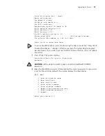
The terminal displays the following information: 

Starting...

        *************************************************

        *                                               *

        *        Switch 8800 Bootrom, Version 113       *

        *                                               *

        *************************************************

Copyright(C) 2000-2004 by 3COM Corporation, Inc.

      Creation date: Jul  5 2004, 10:43:58

      CPU type        : MPC755

      CPU L2 Cache    : 1024KB

      CPU Clock Speed : 400MHz

      BUS Clock Speed : 100MHz

      Memory Size     : 512MB

Flash file system init....done

Board self testing...........................

The board is steady

SlotNo of this board is 4

The MCX is existent

BootRom main system CRC check is OK

82559 register testing is OK

EPLD1 testing is OK

EPLD2 testing is OK

16c2552 register testing is OK

Please check LEDs......................LED testing finished

The switch's Mac address is 0040.9c30.b2d4

Press Ctrl+B to enter Boot Menu... 

The contents displayed on the terminal can vary with different versions of Boot 
ROM. 

If you press 

Ctrl+B

 immediately, the system displays the Boot Menu. If you do not 

press 

Ctrl+B

, the system initiates the program decompression process. At this time 

if you want to access the BOOT Menu, you must reboot the switch. 

1

Press 

Ctrl+B

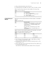
. The system displays:

Initialize flash file system. Please wait!

Password :

Summary of Contents for 3C17500

Page 1: ...witch 8800 Installation Guide Version 3 0 3C17500 14 slot Starter Kit 3C17501 10 slot Starter Kit 3C17502 7 slot Starter Kit and associated modules Part No 10014384 Document Number DUA1750 0AA01 Publi...

Page 2: ...er is applicable You agree not to remove or deface any portion of any legend provided on any licensed program or documentation contained in or delivered to you in conjunction with this User Guide Unle...

Page 3: ...lists icon conventions that are used throughout this guide Table 2 lists text conventions that are used throughout this guide Table 1 Notice Icons Icon Notice Type Description Information note Informa...

Page 4: ...nformation in this guide differs from information in the release notes use the information in the Release Notes These documents are available in Adobe Acrobat Reader Portable Document Format PDF on th...

Page 5: ...ly is installed in the left power slot Switch Backplane The Switch 8800 backplane is part of the integrated chassis and delivers high speed data transfer between the Fabric and I O modules The backpla...

Page 6: ...owing fixed ports Compact Flash CF Port Management 10Base T 100Base TX port 1 Compact Flash port 7 I O module LEDs 2 Management 10BASE T 100BASE TX port 8 SFS LED 3 RS232 485 port 9 RUN LED 4 Console...

Page 7: ...nagement 10Base T 100Base TX port RS232 RS485 port The RS232 RS485 port uses an RJ 45 connector to connect to an external power rack and monitor its status Table 7 lists specifications for the RS232 4...

Page 8: ...modules as described in Table 10 Table 8 Console Port Specifications Specification Description Port connector RJ 45 Port standard Asynchronous EIA TIA 232 Baud rate 9600 bps by default Transmission d...

Page 9: ...ith each installed I O module 1 Port 10GBASE X XENPAK Module The 1 port 10GBASE X XENPAK module provides a single 10 Gbps XENPAK port Figure 2 illustrates the front panel of the 1 port 10GBASE X XENPA...

Page 10: ...ification Description CPU MPC8245 BootROM 512 KB SDRAM 128 MB Dimensions L x W 366 7 x 340 mm 14 5 x 13 4 in Power consumption 60 W Connector SC Number of ports 1 Transmission rate 10 Gbps Transceiver...

Page 11: ...ts 2 Connector XFP LC Port transmission speed 10 Gbps Transceiver cable and maximum transmission distance 3CXFP92 1310 nm 9 125 m single mode optical fiber 10 km 6 mi 3CXFP96 1550 nm 9 125 m single mo...

Page 12: ...multi mode optical fiber 550 m 1804 ft 3CSFP92 1310 nm 9 125 m single mode optical fiber 10 km 6 mi 3CSFP93 RJ 45 category 5 100 m 300 ft 3CSFP97 1550 nm 9 125 m single mode optical fiber 70 km 43 mi...

Page 13: ...ical fiber 10 km 6 mi 3CSFP93 RJ 45 category 5 100 m 300 ft 3CSFP97 1550 nm 9 125 m single mode optical fiber 70 km 43 mi Table 19 Specifications for the 24 Port 1000BASE X SFP Module continued Specif...

Page 14: ...illustrates the 1200 W power supply for the Switch 8800 Figure 7 Switch 8800 Power Supply Table 22 describes the power supply LEDs Table 23 describes the specifications of the power supply for the Sw...

Page 15: ...fans and is located on the right side of the chassis They operate on 48 V DC current Each starter kit includes the appropriate fan assembly Figure 8 illustrates the faceplate of the fan assembly for...

Page 16: ...lane through connectors Fan operation fault signals are collected and transmitted to the system alarm board through the backplane Table 26 Switch 8800 Fan Assembly Specification 7 Slot Chassis 10 Slot...

Page 17: ...to 264 V 47 to 63 Hz Max power consumption all components installed 665 W 975 W 1390 W Environment temperature and humidity 0 to 40 0 C 32 to 104 0 F and 5 to 85 Table 28 Switch 8800 Software Feature...

Page 18: ...n source destination IP address and type of the upper layer protocol Plain text and MD5 text authentication for OSPF and RIP Version 2 DES56 Encryption for SNMP v3 Reliability VRRP QoS Traffic classif...

Page 19: ...mmendations Before installing your switch note the following safety recommendations Switch off the power supply before connecting the cables Keep the switch away from heat sources Do not keep the swit...

Page 20: ...d the power handles when carrying the switch Do not put fingers into the vent of the chassis when carrying the switch Since the power handles and vent have not been designed to bear the weight of the...

Page 21: ...htning damage do the following Install a lightning arrester on the input end of a telephone cable or other external line Ensure that the PGND wire of the chassis is well grounded Ensure that the neutr...

Page 22: ...on screw and floating nuts that are shipped with the switch Installing on a Workbench To install the switch on a workbench take the following precautions Ensure that the workbench is smooth and stable...

Page 23: ...rack 3Com recommends that the ground wire of the switch be connected to the grounding bar of the rack WARNING The resistance between switch chassis and the ground should be less than 1 ohm Connecting...

Page 24: ...guides in the chassis and slide it gently into the slot 5 Push the fan until its positioning pin touches the hole in the chassis 6 Push the ejector levers inward 7 Push the handle bar pin into the hol...

Page 25: ...of the AUX cable into the switch AUX port 2 Connect the DB 25 or DB 9 end of the AUX cable to the serial port of the virtual modem Connecting Module Cables This section describes how to connect electr...

Page 26: ...aised floor Collect all the transit data signal cable connectors and locate them on the floor of the chassis Power cords run out of the rear left of the chassis and on a cable rack or under a raised f...

Page 27: ...e turned off the power before checking your installation Improper connections can injure people or damage components of the switch Table 30 Cable Binding Parameters Cable Bundle Diameter Space Between...

Page 28: ...28 CHAPTER 2 INSTALLING THE SWITCH 8800...

Page 29: ...nected to the switch console port using a console cable Figure 10 Connecting the Switch 8800 to a PC 1 Plug the DB 9 or DB 25 female plug of the console cable into the serial port of the PC or the ter...

Page 30: ...dialog box shown in Figure 12 displays Select the serial port to be used from the Connect using dropdown menu Figure 12 Properties Dialog Box 3 After selecting a serial port click OK The port shown in...

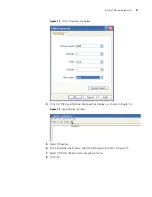
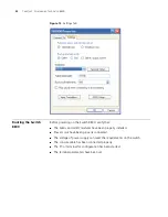
Page 31: ...og Box 4 Click OK The HyperTerminal dialogue box displays as shown in Figure 14 Figure 14 HyperTerminal Window 5 Select Properties 6 In the Properties dialog box select the Settings tab shown in Figur...

Page 32: ...0 verify that The Fabric and all I O modules have been properly installed Power cords have been properly connected The voltage of power supply can meet the requirements on the switch The console cable...

Page 33: ...EPLD1 testing is OK EPLD2 testing is OK 16c2552 register testing is OK Please check LEDs LED testing finished The switch s Mac address is 0040 9c30 b2d4 Press Ctrl B to enter Boot Menu 5 To enter Boo...

Page 34: ...34 CHAPTER 3 CONFIGURING THE SWITCH 8800...

Page 35: ...e with FTP 1 Log in to the system with super user privileges 2 From the SW8800 command line transfer the file from the FTP server to the system using the ftp command 3 Specify the file to boot the sys...

Page 36: ...ork connection between the Ethernet port on the Switch 8800 Fabric module and the FTP TFTP server In addition you should verify that the file you want to use for the upgrade procedure is on the FTP TF...

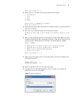
Page 37: ...ter Boot Menu displays After five seconds the system begins program decompression If you want to access the BOOT Menu after this you must reboot the switch 1 Press Ctrl B The system displays Initializ...

Page 38: ...o previous field D quit boot device fei0 processor number 0 host name 8512 file name 88002 app 88003 app inet on ethernet e 192 168 25 210 inet on backplane b 192 168 25 158 host inet h 192 168 25 2 g...

Page 39: ...interface lo0 done boot device fei unit number 0 processor number 0 host name 8512 file name 88003 04 app inet on ethernet e 192 168 25 210 ffffff00 inet on backplane b 192 168 25 158 host inet h 192...

Page 40: ...After passing the negotiation the sending program begins to send the packet The receiving program checks the packet according to the negotiated means after receiving a complete packet The acknowledge...

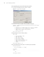
Page 41: ...h 8800 you must change the baud rate at the configuration terminal so that the two baud rates are the same When the baud rates are the same the Serial Submenu displays SERIAL SUBMENU 1 Download file t...

Page 42: ...terface and boot 2 Download file to Flash through serial interface 3 Modify serial interface boot parameter 0 Return to main menu Enter your choice 0 3 0 13 Select option 0 to return to the Main Menu...

Page 43: ...the manufacturer s instructions and that it is enabled and pointing to the correct directory To upgrade using TFTP 1 Verify that you are logged in with super user privileges 2 From the Switch 8800 co...

Page 44: ...is board is 4 The MCX is existent BootRom main system CRC check is OK 82559 register testing is OK EPLD1 testing is OK EPLD2 testing is OK 16c2552 register testing is OK Please check LEDs LED testing...

Page 45: ...nfiguration information The Switch 8800 does not synchronize versions of the application file between Fabrics Therefore you must manually download the application file to one Fabric then copy the appl...

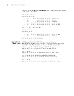
Page 46: ...b 10 2003 11 35 10 88003 01 app 1 drw Mar 16 2003 12 16 00 logfile 250352 KB total 234680 KB free Copying Files to Compact Flash Use the copy command in the format copy source filename destination fil...

Page 47: ...he power cord 3 Loosen the captive screws on both sides of the power supply 4 Support the power supply with one hand and gently pull the handle with the other hand until it slides out of the slot 5 If...

Page 48: ...nt or severe electrical shock Replacing I O Modules To replace an I O module you need An antistatic wrist strap A screwdriver To remove a module 1 Remove all the cables from the module to be removed 2...

Page 49: ...h both hands pull out the ejector levers on the fan assembly to separate the fan assembly connector from the backplane 3 Pull the fan gently along the guides of the slot to remove it 4 With both hands...

Page 50: ...50 CHAPTER 5 MAINTAINING HARDWARE...

Page 51: ...erminal after the Switch 8800 is powered on check that The power system is working normally The Fabric is working normally The console cable has been connected to the console port on the Fabric If thi...

Page 52: ...wer switch is in the ON position The power supply is installed right side up The FAIL LED is on Verify the following The correct power voltage is in use 90 to 264 V AC 50 to 60 Hz The air filter prote...

Page 53: ...resetting the module if the ALM LED remains off the module may not be connected to the power source Check that the module has been properly installed in the correct position Table 33 Fan LEDs on the F...

Page 54: ...54 CHAPTER 6 TROUBLESHOOTING...

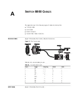
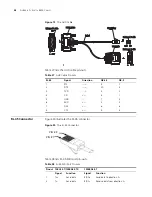
Page 55: ...ors Figure 18 The Console cable Table 36 lists console cable pin outs AUX Cable Figure 19 illustrates the AUX cable Table 36 Console Cable Pin outs RJ 45 Signal Direction DB 25 DB 9 1 RTS 4 7 2 DTR 20...

Page 56: ...ion DB 25 DB 9 1 RTS 4 7 2 DTR 20 4 3 TXD 2 3 4 CD 8 1 5 GND 7 5 6 RXD 3 2 7 DSR 6 6 8 CTS 5 8 Enlarged B side Enlarged B side Enlarged A side Enlarged A side Enlarged C side Enlarged C side DB25 Male...

Page 57: ...Receive data from direction B 7 Reserved BIDD Send data to direction D 8 Reserved BIDD Receive data from direction D Table 39 RJ 45 MDI X Port Pinouts Pinout 10BASE T 100 BASE TX 1000BASE T Signal Fun...

Page 58: ...58 APPENDIX A SWITCH 8800 CABLES...

Page 59: ...n 3Com Extended Warranty and Professional Services is available at http www 3com com Contact your authorized 3Com reseller or 3Com for additional product and support information Troubleshoot Online Yo...

Page 60: ...duct directly to 3Com for repair you must first obtain a return authorization number RMA Products sent to 3Com without authorization numbers clearly marked on the outside of the package will be return...

Page 61: ...o Ecuador Dominican Republic 1 800 988 2112 0 810 444 3COM 1 800 998 2112 1 800 998 2112 1 800 998 2112 52 5 201 0010 1 800 998 2112 1 800 998 2112 0800 13 3COM 1 800 998 2112 AT T 800 998 2112 AT T 8...

Page 62: ...62 APPENDIX B OBTAINING SUPPORT FOR YOUR SWITCH 8800...

Reviews: