92
C
HAPTER
6: S
PANNING
T
REE
P
ROTOCOL
(STP)
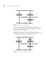
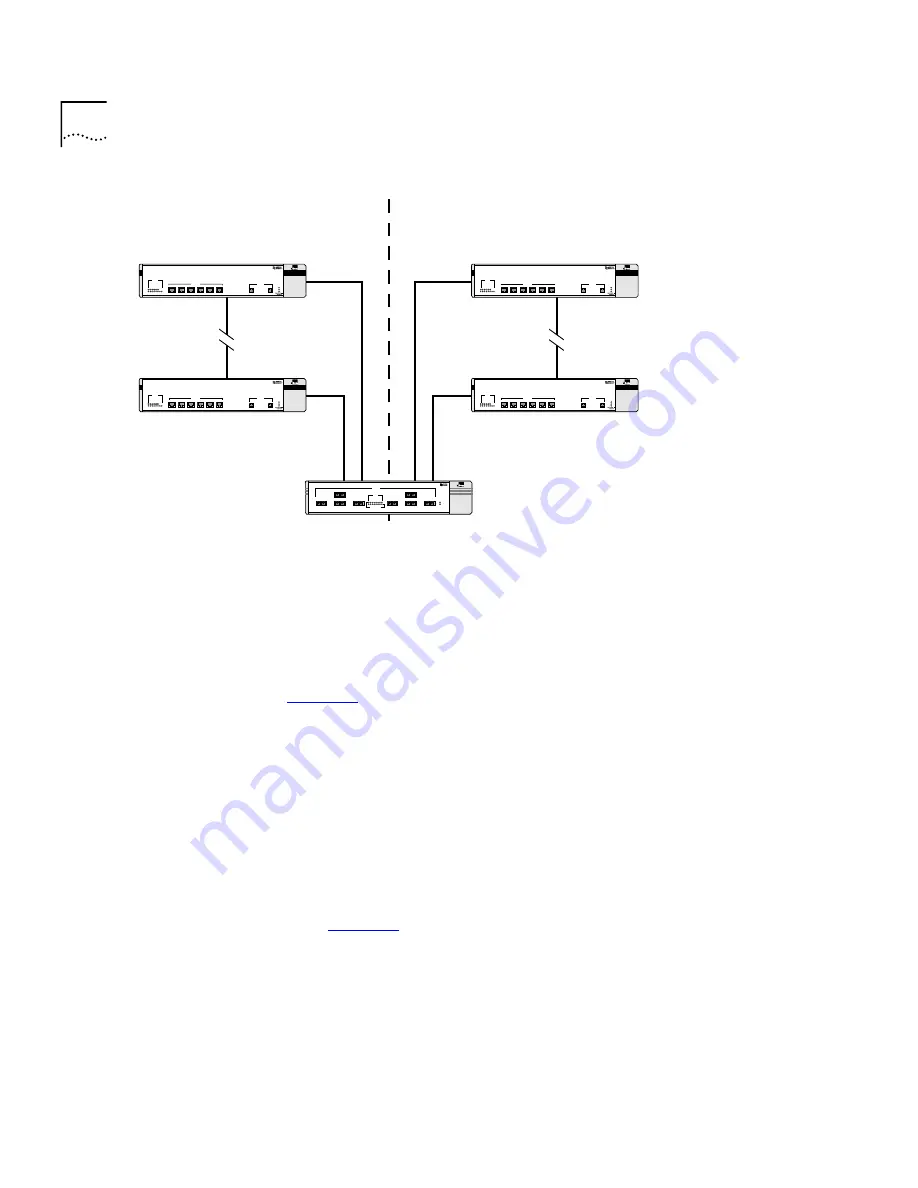
Figure 16
Multiple Spanning Tree Domains
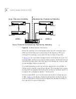
When the switches in this configuration start up, STP configures each
STPD such that there are no active loops in the topology. STP could
configure the topology in a number of ways to make it loop-free.
In
Figure 16
, the connection between Switch A and Switch B is put into
blocking state, and the connection between Switch Y and Switch Z is put
into blocking state. After STP converges, all the VLANs can communicate,
and all bridging loops are prevented.
The VLAN
Marketing
, which has not been assigned to either STPD1 or
STPD2, communicates using all five switches. The topology has no loops,
because STP has already blocked the port connection between Switch A
and Switch B, and between Switch Y and Switch Z.
Within a single STPD, you must be extra careful when configuring your
VLANs.
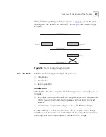
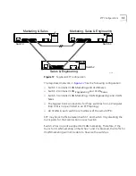
Figure 17
illustrates a network that has been incorrectly set up
using a single STPD so that the STP configuration disables the ability of
the switches to forward VLAN traffic.
Sales, Personnel, Marketing
STPD 1
STPD 2
Manufacturing, Engineering, Marketing
Sales, Personnel, Manufacturing, Engineering, Marketing
Switch A
Switch Y
Switch Z
Switch M
Switch B
91_009
Summary of Contents for 3C17705
Page 10: ...GLOSSARY INDEX INDEX OF COMMANDS 3COM CORPORATION LIMITED WARRANTY EMC STATEMENTS ...
Page 14: ...14 ABOUT THIS GUIDE ...
Page 32: ...32 CHAPTER 2 INSTALLATION AND SETUP ...
Page 62: ...62 CHAPTER 3 ACCESSING THE SWITCH ...
Page 80: ...80 CHAPTER 4 VIRTUAL LANS VLANS ...
Page 86: ...86 CHAPTER 5 FORWARDING DATABASE FDB ...
Page 98: ...98 CHAPTER 6 SPANNING TREE PROTOCOL STP ...
Page 110: ...110 CHAPTER 7 QUALITY OF SERVICE QOS ...
Page 124: ...124 CHAPTER 8 STATUS MONITORING AND STATISTICS ...
Page 130: ...130 CHAPTER 9 USING THE WEB INTERFACE ...
Page 136: ...136 CHAPTER 10 SOFTWARE UPGRADE AND BOOT OPTIONS ...
Page 156: ...156 APPENDIX C TROUBLESHOOTING ...
Page 162: ......
Page 176: ...176 INDEX ...
Page 180: ...180 INDEX OF COMMANDS ...


