142
C
HAPTER
5: C
ONFIGURING
P
ATH
B
UILDER
S600 M
ODULES
, P
ORTS
,
AND
A
PPLICATIONS
Least Delay Link
—The port number of the fastest link in the group.
Oper. LInk Delay
—Operational link delay; the actual value of the link differential
delay:
0-70 msec
for T1,
0-50 msec
for E1.
Tx Avable. Cell Rate (cps)
—The available cell rate for active Tx links in this
group:
0-28,728 cps
for DS1, M=128;
0-35,920 cps
for E1, M=128. The available
cell rate indicates how much bandwidth can be carried across the group. It varies,
depending on how many links in the group are actually working.
Rx Avable Cell Rate (cps)
—The available cell rate for active Rx links in this group:
0-28,728 cps
for DS1, M=128;
0-35,920 cps
for E1, M=128. The available cell rate
indicates how much bandwidth can be carried across the group. It varies,
depending on how many links in the group are actually working.
# Tx Configured Links
—The number of configured transmit links.
# Rx Configured Links
—The number of configured receive links.
#Tx Active links
—The number of active transmit links.
#Rx Active links
—The number of active receive links.
Configuring the DS1 (or
E1) UNI Card
The only type of configuration you can perform on the DS1 UNI or E1 UNI card is
to put it in service or out of service. To put the DS1/E1 UNI card in service or out of
service, follow these steps:
1
From the List Card menu, shown earlier in Figure 80, select the number
corresponding to the slot in which the DS1 UNI or E1 UNI card is installed to
display the DS1 UNI or E1 UNI Configuration menu, shown earlier in Figure 90.
2
From the DS1 UNI or E1 UNI Configuration menu, select
[5] Card Information
to
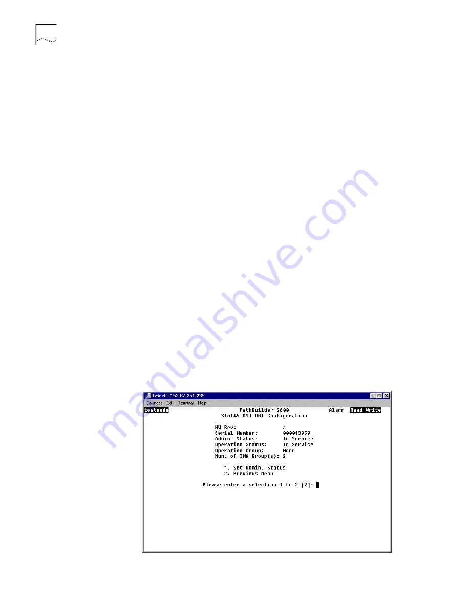
display the Card Configuration menu. Figure 104 shows the DS1 UNI Card
Configuration menu. The E1 UNI Card Configuration menu is the same.
3
Select
[1] Set Admin Service
and enter
[2]
to put the card in service or
[1]
to take it
out of service.
Figure 104
DS1 UNI Card Configuration Menu
Summary of Contents for 3C63100-AC-C - PathBuilder S600...
Page 8: ...INDEX 3COM CORPORATION LIMITED WARRANTY ...
Page 14: ...xiv CHAPTER SUPPLEMENTARY REGULATORY INFORMATION ...
Page 18: ...18 ABOUT THIS GUIDE ...
Page 28: ...28 CHAPTER 1 SYSTEM DESCRIPTION ...
Page 74: ...74 CHAPTER 3 GETTING STARTED ...
Page 230: ...230 INDEX ...


