Step 4: Connect I/O Cabling and Wiring
37
Once you have connected the module, verify the front-panel indicator sequence.
The startup LED sequence and module-specific LEDs for the E3 UNI module are the
same as those for the D3 UNI module. See “Connecting a DS3 UNI Module”
above, for details.
Connecting an
OC3/STM-1 UNI
Trunk/Port Module
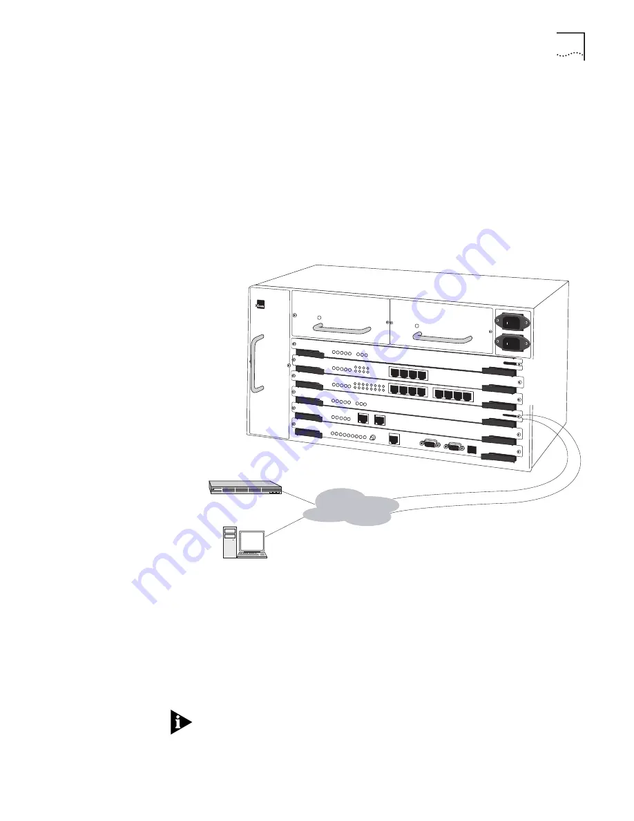
Connect the OC3/STM-1 UNI module using the Internal SC type connector. As
shown in Figure 11, the OC3-STM-1 UNI module supports two types of fiber optic
cable.
n
Use multi-mode cable to generate UNI traffic over a port interface.
n
Use single-mode cable to generate UNI traffic over a trunk interface.
Figure 11
OC3/STM-1 UNI Module Connection
Once you have connected the module, verify the front-panel indicator sequence.
The startup LED sequence and module-specific LEDs for the OC3/STM-1 UNI
module are the same as those for the D3 UNI module. See “Connecting a DS3 UNI
Module” earlier in this chapter, for details.
Connecting a DS1/E1
UNI with IMA Module
Connect the DS1 UNI with IMA module or the E1 UNI with IMA module using the
RJ-48 connectors (with integrated CSU for the DS1 module, with no CSU for the
E1 module), as shown in Figure 12.
If you are using a G703 coax physical connection to connect the E1 line to the
interface, you must use the E1 Balun Adapter (part number 3C63904) for proper
resistance.
Slot 6
Slot 5
Slot 4
OC3 UNI Multi Mode Port
OC3 UNI Single Mode Trunk
ATM
PathBuilder S600
Summary of Contents for 3C63100-AC-C - PathBuilder S600...
Page 8: ...INDEX 3COM CORPORATION LIMITED WARRANTY ...
Page 14: ...xiv CHAPTER SUPPLEMENTARY REGULATORY INFORMATION ...
Page 18: ...18 ABOUT THIS GUIDE ...
Page 28: ...28 CHAPTER 1 SYSTEM DESCRIPTION ...
Page 74: ...74 CHAPTER 3 GETTING STARTED ...
Page 230: ...230 INDEX ...


