38
C
HAPTER
2: I
NSTALLATION
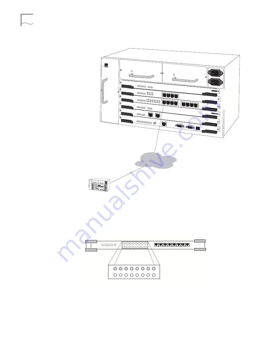
Figure 12
DS1/E1 UNI with IMA Module Connection
Once you have connected the module, verify the front-panel indicators. As shown
in Figure 13, the DS1/E1 UNI with IMA module features eight pairs of port
indicator LEDs in addition to the common system front panel indicators—each pair
corresponds to one of the eight RJ48 interfaces on the DS1/E1 UNI module.
Figure 13
DS1/E1 UNI LEDs
n
The green indicator light illuminates to show that the port is in service.
n
The red indicator light illuminates to show that the port is not in service.
PathBuilder S600
Slot 6
Slot 5
Slot 4
DS1/E1
n
x T1 or E1
PathBuilder S600
PathBuilder S600
ATM
Summary of Contents for 3C63100-AC-C - PathBuilder S600...
Page 8: ...INDEX 3COM CORPORATION LIMITED WARRANTY ...
Page 14: ...xiv CHAPTER SUPPLEMENTARY REGULATORY INFORMATION ...
Page 18: ...18 ABOUT THIS GUIDE ...
Page 28: ...28 CHAPTER 1 SYSTEM DESCRIPTION ...
Page 74: ...74 CHAPTER 3 GETTING STARTED ...
Page 230: ...230 INDEX ...


