Step 4: Connect I/O Cabling and Wiring
57
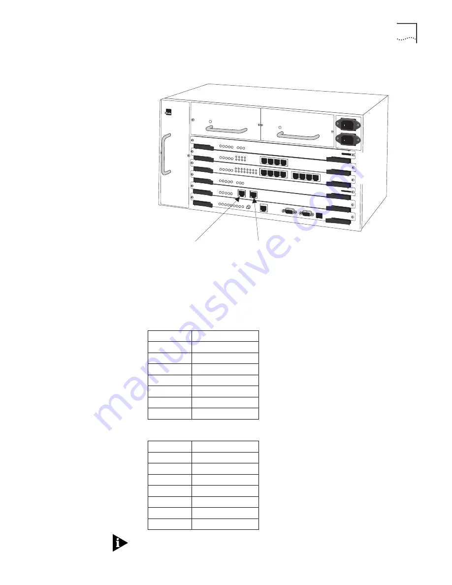
Figure 26
BITS Clock Connection (STX Module)
Table 18 and Table 19 list the connector pinouts for the input and output
connectors.
This feature is currently available for North American, DSI, Standard carrier signals.
Table 18
STX Module BITS Clock Input Connector Pinouts
PIN 1
Receive Ring
PIN 2
Receive Tip
PIN 3
PIN 4
Transmit Tip
PIN 5
Transmit Ring
PIN 6
PIN 7
PIN 8
Table 19
STX Module BITS Clock Output Connector Pinouts
PIN 1
Receive Ring
PIN 2
Receive Tip
PIN 3
PIN 4
Transmit Tip
PIN 5
Transmit Ring
PIN 6
PIN 7
PIN 8
PathBuilder S600
Slot 6
Slot 5
Slot 4
1.544 Mbps
All Ones
RJ48 PIN 4 -Transmit Tip
RJ48 PIN 5 - Transmit Ring
1.544 Mbps
All Ones
RJ48 PIN 1 - Receive Ring
RJ48 PIN 2 - Receive Tip
Summary of Contents for 3C63100-AC-C - PathBuilder S600...
Page 8: ...INDEX 3COM CORPORATION LIMITED WARRANTY ...
Page 14: ...xiv CHAPTER SUPPLEMENTARY REGULATORY INFORMATION ...
Page 18: ...18 ABOUT THIS GUIDE ...
Page 28: ...28 CHAPTER 1 SYSTEM DESCRIPTION ...
Page 74: ...74 CHAPTER 3 GETTING STARTED ...
Page 230: ...230 INDEX ...


