background image

Supported Applications

91

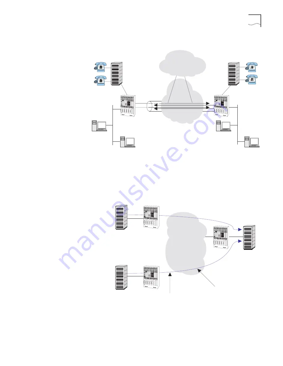
Figure 53   

Integrated PathBuilder S700 Application

Drop-and-Insert DS0 channels can also be allowed to transit the entire path. This 
provides DS0 to DS0 connectivity between end locations. Structured DS0s can be 
groomed to be combined through an ATM network allowing end to end DS0 
switching as shown in Figure 54.

Figure 54   

Structured DS0 Combining

ATM Network

Voice

DS0 = 1-6

LAN

Data

Drop

DS0 = 6

PBX or Key

System

PBX or Key

System

Ethernet

LAN

Ethernet

LAN

Public Switched

Telephone

Network

PathBuilder S700

PathBuilder S700

DS1

DS1

Up to 24 Timeslots

ATM Network

10 DS0

10 DS0

 PBX - Private Branch Exchange
VCC - Virtual Channel Connection 

Structured DS0

Grooming

PathBuilder S700

PathBuilder S700

PathBuilder S700

Summary of Contents for 3C63400-3AC-C - PathBuilder S700 Switch

Page 1: ...http www 3com com PathBuilder S700 WAN Access Switch Reference Guide Release 2 03 Part No 3C64917 010 12197 0001 Published November 1998 ...

Page 2: ... Use duplication or disclosure by the Government is subject to restrictions as set forth in subparagraph c 1 ii for Restricted Rights in Technical Data and Computer Software Clause at 48 C F R 52 227 7013 3Com Corporation 5400 Bayfront Plaza Santa Clara California 95052 8145 For civilian agencies Restricted Rights Legend Use reproduction or disclosure is subject to restrictions set forth in subpar...

Page 3: ...nventions 2 Related Documentation 3 1 SYSTEM DESCRIPTION Introducing the PathBuilder S700 5 PathBuilder S700 Features 5 Key Features of the STX Module 5 PathBuilder S700 Architecture 6 Specifications 8 Options and Parts List 12 2 INSTALLATION Receiving and Inspecting the PathBuilder S700 15 Installation Overview 15 Site Requirements 16 Step 1 Install the Shelf in the Rack 16 Step 2 Connect AC or D...

Page 4: ... Menu Hierarchy 60 Using the Menus to Change Settings 60 Alarm Indicator 60 Performing Initial Configuration 61 Setting up Communication Parameters 62 Configuring the Local Host IP Address 63 Configuring Trap Clients 66 Configuring the Default Gateway 68 Configuring In band Management 68 In band Management via the 10Base T Port on the Near end MCPU Card 68 In band Management via the Near end Dual ...

Page 5: ...93 Structured versus Unstructured Summary 95 Ethernet and Voice Application 95 Frame Application 99 DXI Mode 1A 99 Frame Relay Interworking Functions 102 HDLC SDLC 103 5 CONFIGURING PATHBUILDER S700 MODULES PORTS AND APPLICATIONS Viewing and Configuring System Information 105 Specifying General System Information 106 Managing the System Clock 107 Alarm Conditions that Cause Clock Source Failure 11...

Page 6: ...uring DS1 E1 UNI Ports 135 Activation Deactivation Bit Error Rates 137 Configuring UNI and IMA Groups 138 Adding UNI Groups 138 Adding IMA Groups 140 Viewing and Modifying IMA and UNI Groups 142 Configuring Virtual Interfaces for IMA Groups 143 Deleting IMA and UNI Groups 143 Viewing IMA Link Status 145 Viewing IMA Group Status 147 Configuring DS1 UNI or E1 UNI Cards 150 Configuring Ethernet Modul...

Page 7: ...l Circuits 204 Viewing Virtual Circuit Statistics 204 6 PATHBUILDER S700 DIAGNOSTICS AND PERFORMANCE MONITORING Managing System Alarms 205 Viewing and Clearing Current Alarms 205 PathBuilder S700 Alarm Messages 207 MCPU and STX Module System Alarms 207 Alarms Common to Several Modules 211 DS1 E1 UNI Module Alarms 213 DSX 1 E1 CBR Module Alarms 218 QSIM FAM Alarms 219 Working with History Alarms 21...

Page 8: ... Circuit Statistics by Circuit 241 Conforming Non Conforming Cell Counters 243 Viewing Virtual Circuit Statistics by Port Group 244 A TECHNICAL SUPPORT Online Technical Services 247 World Wide Web Site 247 3Com FTP Site 247 3Com Bulletin Board Service 248 Access by Analog Modem 248 Access by Digital Modem 248 3ComFacts Automated Fax Service 248 Support from Your Network Supplier 248 Support from 3...

Page 9: ...ditions of Acceptability When installed in the end use equipment the following are among the considerations to be made 1 The units shall be installed in compliance with enclosure mounting spacing casualty and segregation requirements of the ultimate application 2 These units have been judged on the basis of the required spacings of UL 1950 D3 deviations edition CSA 22 2 No 950 M89 and EN 60950 198...

Page 10: ...d to provide reasonable protection against such interference when operated in a commercial environment Operation of this equipment in a residential area is likely to cause interference in which case the user at his own expense will be required to take whatever measures may be required to correct the interference These tests were conducted with shielded communications cables with metal connector ho...

Page 11: ...tions to the host when other option cards are introduced which use or generate a hazardous voltage the minimum creepages and clearances specified in the table below are maintained A hazardous voltage is one which exceeds 42 2V peak AC or 60V DC If you have any doubt seek advice from a component engineer before installing other adapters into the test equipment The larger distance shown in parenthes...

Page 12: ... to be connected to the telephone network or premises wiring using a compatible modular jack which is Part 68 compliant See installation instructions for details If this device causes harm to the telephone network the telephone company will notify you in advance that temporary discontinuance of service may be required The telephone company may request that you disconnect the equipment until the pr...

Page 13: ...Connection of 2 Mbit s Unstructured Leased Lines CTR13 Connection to 2 Mbit s Structured Leased Lines EN 60950 Safety of Information Technology Equipment including Electrical Business Equipment EN 41003 Particular safety requirements for electrical equipment to be connected to Telecom networks WARNING This customer equipment is to be installed and maintained by service personnel as defined by AS N...

Page 14: ...xiv CHAPTER SUPPLEMENTARY REGULATORY INFORMATION ...

Page 15: ...ooking for Turn to Descriptions of the features and benefits of the PathBuilder S700 Chapter 1 System specifications Chapter 1 Installation instructions Chapter 2 Information about how to get started using the PathBuilder S700 Chapter 3 Instructions for using the PathBuilder S700 menus Chapter 3 Information about the specific modules and applications you can use with the PathBuilder S700 Chapter 4...

Page 16: ...s guide always gives the full form of a command in uppercase and lowercase letters However you can abbreviate commands by entering only the uppercase letters and the appropriate value Commands are not case sensitive Screen displays This typeface represents information as it appears on the screen The words enter and type When you see the word enter in this guide you must type something and then pre...

Page 17: ...ions and issues found in the release PathBuilder Switch Manager User Guide Describes how to use PathBuilder Switch Manager to configure and manage PathBuilder WAN access switches Using PathBuilder Switch Manager you can configure shelf device and circuit information use a loopback panel to diagnose port cards view line and interface statistics and perform administrative functions such as configuri...

Page 18: ...4 ABOUT THIS GUIDE ...

Page 19: ...ccess T1 or E1 ports 14 DS3 or E3 ports or 14 OC3 STM 1 ports n High ATM backplane capacity 3 2 Gbps n Supports proven technology queuing buffering traffic shaping traffic policing early packet discard and multicasting See Key Features of the STX Module below for details n Resiliency supports load sharing power supplies hot swappable common components MCPU and STX and application modules selected ...

Page 20: ...nge of interfaces and support a comprehensive set of applications The core component of the unit is a 3 2 Gbps cell bus backplane where all traffic is carried in the form of ATM cells The PathBuilder S700 accommodates up to six power supplies AC 110 220 VAC and DC 48 VDC in a load sharing configuration The overall design philosophy of the PathBuilder S700 is to facilitate the transfer of cells on ...

Page 21: ... selected rear redundant application modules T1 E1 and DS3 E3 You can use front connector modules identical to those used in the PathBuilder S600 as well as the rear redundant modules but only the rear connector types will support the redundant operation available in subsequent releases The S700 supports the following ATM and application modules n DS3 UNI module front or rear connector n E3 UNI mo...

Page 22: ...erature 0 to 45ºC Storage Temperature 40 to 70ºC Humidity 95 40ºC noncondensing Altitude 14 000 ft or 4 300 meters Regulatory Compliance FCC FCC Part 15 rules for a Class A computing device FCC Part 68 Emissions EN55022 EN50082 1 CTR 12 CTR 13 Austel TS 001 Austel AS 3260 Safety UL listed UL 1950 and 1459 VDE TUV EN 60950 EN41003 CSA 22 2 Austel AS NZS35 48 Physical Shelf Dimensions 22 75 x 19 x 1...

Page 23: ...RUM Inverse Multiplexing for ATM IMA Specification Version 1 0 ANSI T1 107 1988 ANSI T1 403 ANSI T1 403 ANSI T1 403 RFC 1483 1490 RFC 826 RFC 1042 RFC 1577 IEEE 802 1 IEEE 802 3 AT T PUB 54016 AT T PUB 62411 ITU T G 821 ITU T G 703 ITU T G 704 Frame Relay Forum Specifications 5 and 8 ATM User to Network Interface UNI Modules Interfaces DS3 UNI Coax BNC E3 UNI Coax BNC OC3 UNI MMF SMF SC STM 1 UNI ...

Page 24: ...fic Shaping Bulk shaping Per VC VP shaping Per VC shaping Ethernet FAM QSIM HSIM Traffic Policing Per VC DS1 E1 UNI with Integrated Inverse Multiplexing for ATM IMA Modules Number of Interfaces nx8 n 1 to 8 software selectable for individual T1 E1 UNIs or as logical IMA group 1 link Connector Type RJ 48 connectors Integrated CSU Yes for DS1 Line Coding B8ZS for T1 HDB3 for E1 Line Framing ESF SF D...

Page 25: ...er data field Address Table Size 8192 entries 4096 per port ATM Protocols AAL5 RFC 1483 Class of Service VBR UBR VPI VCI Up to 512 per module Traffic Shaping Multiple levels with PCR SCR and MBS settings Frame Data Modules Interface Up to 8 T1 120 ohm FAM 4 V 35 RS 449 EIA530 X 21 QSIM 1 HSSI HSIM Speeds line rate T1 56 64 Kbps to 1 5 Mbps V 35 RS 422 449 up to 8 Mbps each HSSI 20 Mbps Packet Prot...

Page 26: ...me Relay SDLC HDLC 3C63105 4DSX 4 Port DSX 1 CBR Module 3C63405 4DSX PathBuilder S700 Rear Redundant 4 Port DSX 1 CBR Module 3C63105 8DSX 8 Port DSX 1 CBR Module 3C63405 8DSX PathBuilder S700 Rear Redundant 8 Port DSX 1 CBR Module 3C63105 4E1 4 Port E1 CBR Module 3C63405 4E1 PathBuilder S700 Rear Redundant 4 Port E1CBR Module 3C63105 8E1 8 Port E1 CBR Module 3C63405 8E1 PathBuilder S700 Rear Redun...

Page 27: ...DS1 E1 Cable RJ48 Shielded Crossover to RJ48 8M 25Ft 3C63904 E1 Balun Adapter RJ48 120 ohm to Coax 75 ohm 2M 6Ft 3C63905 Fiber Cable SC Multi mode to SC 8M 25Ft 3C63906 Fiber Cable SC Multi mode to FC 8M 25Ft 3C63907 Fiber Cable SC Multi mode to ST 8M 25Ft 3C63908 Fiber Cable SC Single mode to SC 8M 25Ft 3C63909 Fiber Cable SC Single mode to FC 8M 25Ft 3C63910 Fiber Cable SC Single mode to ST 8M 2...

Page 28: ...14 CHAPTER 1 SYSTEM DESCRIPTION ...

Page 29: ...s Receiving and Inspecting the PathBuilder S700 When you receive the PathBuilder S700 unpack it and inspect the unit for any damage that might have occurred during shipment Inventory the equipment against the shipping notice Save the boxes and packing materials in the event there is damage or anything needs to be reshipped at a future date If anything is damaged or missing contact the shipper and ...

Page 30: ...s a fan tray and a minimum gap of one RU rack unit is required between the chassis and any convection cooled equipment CAUTION Many of the integrated circuits on the modules are sensitive to static electricity Do not handle the plug in modules without wearing a properly grounded antistatic wrist strap When removing the modules from the shelf place them printed circuit side down on a nonconducting ...

Page 31: ... weighs 95 pounds we recommend that two people install the unit in the rack Step 2 Connect AC or DC Power AC DC power connections are located at the rear of the PathBuilder S700 shelf Table 6 lists the specifications for the AC DC Source PathBuilder S700 19 or 23 13 Rows 22 75 One rack unit space required above and below the unit for clearance Caution Table 6 AC DC Source Specifications Input Powe...

Page 32: ...across the backplane to the other modules Make sure that the power supply modules and the fan tray are in the shelf and that they are fully seated in their backplane connectors CAUTION Before servicing the unit and handling AC DC power leads disconnect all power supply cords Always have a partner close by who is familiar with first aid for electrical shock WARNING DC Units are to be installed only...

Page 33: ... Connect AC or DC Power 19 Figure 4 illustrates the location of the AC power plugs and switch on the rear of the unit Figure 4 PathBuilder S700 AC Power Input TX RX TX RX TX RX TX RX AC Power Input AC Switch ...

Page 34: ...CHAPTER 2 INSTALLATION Figure 5 illustrates the location and pinouts for the DC connector block on the rear of the unit Figure 5 PathBuilder S700 DC Power Input TX RX TX RX TX RX TX RX DC Power Input GND Ð ...

Page 35: ...TX module which will be supported in subsequent releases n Install any one of the following application modules in slot 5 18 n DS3 UNI n E3 UNI n OC3 STM 1 UNI n DS1 UNI with IMA n E1 UNI with IMA n Ethernet n DSX 1 CBR n E1 CBR n QSIM Quad Serial Interface Module n HSIM HSSI Module n FAM Frame Access Module To minimize reconfiguration of modules to implement future redundancy capabilities we reco...

Page 36: ...nfiguration with all of the associated cabling connected Figure 6 Sample Full System Configuration PathBuilder S700 RX In TX Out 75 ohm coax DS3 E3 CSU or CPE DS3 E3 Service TX Out TX In Slot 1 Slot 18 VT100 T Initial Management Connection to Add an IP Address for LAN Management Network Management Station OC3 UNI Multi Mode OC3 UNI Single Mode ATM DS1 E1 n x T1 or E1 PathBuilder S700 PathBuilder S...

Page 37: ...3 UNI or E3 UNI Module Connect the DS3 UNI or E3 UNI module to a DS3 or E3 repeater using the female BNC connectors as shown in Figure 8 The maximum coax run is 450 feet for DS3 and 1200 feet for E3 The transmitter in the DS3 UNI Module includes selectable LBO Line Build Out to adjust the output signal to cable runs of 0 255 or 225 450 feet Select the LBO during card configuration from the local t...

Page 38: ...ation of the state is needed LOF RED Powers up in the off state and illuminates when a LOF Loss of Frame condition is detected on the incoming DS3 E3 The LOF LED is off when the signal is in frame It reflects the LOF state of the DS3 E3 in real time no integration of the state is needed LOCD RED Powers up in the off state and illuminates when a LOCD Loss of Cell Delineation condition is detected o...

Page 39: ...and Wiring 25 Figure 9 DS3 E3 UNI Module LEDs PathBuilder S700 Power Up 3 1 2 Diagnostic Running Power Inservice Fail Test Active LOS LOF LOCD Power On Test Complete Good DS3 E3 OC3 STM 1 Good ATM Cell Delineation Slot 1 Slot 18 ...

Page 40: ...mode cable to generate UNI traffic over a trunk interface Figure 10 OC3 STM 1 UNI Single mode or Multi mode Module Connection Once you have connected the module verify the front panel indicator sequence The startup LED sequence and module specific LEDs for the OC3 STM 1 UNI module are the same as those for the D3 UNI and E3 UNI module See Connecting a DS3 UNI or E3 UNI Module and Figure 9 earlier ...

Page 41: ... how to connect rear redundant DS1 E1 UNI modules see Connecting Rear Redundant Modules later in this chapter If you are using a G703 coax physical connection to connect the E1 line to the interface you must use the E1 Balun Adapter part number 3C63904 for proper impedance Figure 11 DS1 E1 UNI with IMA Module Connection Once you have connected the module verify the front panel indicators As shown ...

Page 42: ... or through a hub as shown in Figure 13 Table 8 lists the RJ48 connector pinouts The cable runs from the PathBuilder S700 Ethernet ports to the Ethernet LAN connections must be no longer than 100 meters in compliance with EIA TIA standards for 10BaseT The cable lengths should include service loops at the ends and the complete cable route distances PathBuilder S700 Slot 1 Slot 18 Table 8 Ethernet M...

Page 43: ... flash Link Port1 GREEN This LED will illuminate when properly connected to the Ethernet cable otherwise it will be off TX Port 2 GREEN This is a transmit to the cable activity indicator For each frame sent to the cable the LED is momentarily flashed RX Port2 GREEN This is a Receive from the cable activity indicator For each frame received from the cable the LED will momentarily flash Link Port 2 ...

Page 44: ... as described in this section and rear redundant modules which you connect from the rear of the unit For details about how to connect rear redundant DSX 1 E1 CBR modules see Connecting Rear Redundant Modules later in this chapter PathBuilder S700 Power Up 1 2 Power Inservice Fail Test Fwd ATM Tx Rx Link Tx Rx Link Power On Test Complete Bridge Data If Blinking Blinks With Data Should Be On When Pr...

Page 45: ...an typically make connections locally to DTE equipment without DSU CSUs as long as the equipment supports a direct T1 interface and can recover T1 signal See Figure 15 Figure 15 DSX 1 E1 CBR Module Connections You can make connections from the E1 CBR module locally to DTE equipment as long as the equipment supports a direct E1 interface and can recover an E1 signal Once you have connected the DSX ...

Page 46: ...ch pair corresponds to one of the ports on the DSX 1 E1 CBR module n The green indicator light illuminates to show that the port has been placed in service n The red indicator light illuminates to show an OOF or LOS condition on the port PathBuilder S700 3 1 2 Power Inservice Fail Test Active Slot 1 Slot 18 Port is Out of Service Port is in Service Port has OOF or LOS Condition Out of Service Port...

Page 47: ... V 35 n DTE DCE EIA530 n DTE DCE RS 422 n DTE DCE X 21 To connect the QSIM attach the appropriate cable to one of the four ports using the 60 pin amphenol connector as shown in Figure 17 Figure 17 QSIM Connection Table 10 Table 11 Table 12 Table 13 Table 14 Table 15 Table 16 Table 18 and Table 17 describe the connector pinouts PathBuilder S700 V 35 EIA530 RS 422 Router ...

Page 48: ...5 Conn Direction For QSIM Frame GND 46 A Circuit GND 45 B RTS 42 C Out CTS 35 D In DSR 34 E In DCD 33 F In DTR 43 H Out LL not used 44 K Out SD 18 P Out SD 17 S Out RD 28 R In RD 27 T In SCTE 20 U Out SCTE 19 W Out SCR 26 V In SCR 25 X In SCT 24 Y In SCT 23 AA In Shorting GR 1 48 49 Shorting GR 2 50 51 52 Shorting GR 3 53 54 55 56 ...

Page 49: ...nn Pin on V 35 Conn Direction For QSIM Frame GND 46 A Circuit GND 45 B RTS 35 C In CTS 42 D Out DSR 43 E Out DCD 44 F Out DTR 34 H In LL not used 33 K In SD 28 P In SD 27 S In RD 18 R Out RD 17 T Out SCTE 26 U In SCTE 25 W In SCR 22 V Out SCR 21 X Out SCT 20 Y Out SCT 19 AA Out Shorting GR 1 48 49 Shorting GR 2 50 51 Shorting GR 3 53 54 55 56 ...

Page 50: ...ction For QSIM Frame GND 46 1 Circuit GND 15 16 45 19 20 37 RTS 9 10 7 25 Out CTS 1 2 9 27 In DSR 3 4 11 29 In DCD not used see DCE cable 5 6 13 31 In DTR 7 8 12 30 Out LL not used 44 10 Out SD 11 4 Out SD 12 22 Out RD 28 6 In RD 27 24 In SCTE 13 17 Out SCTE 14 35 Out SCR 26 8 In SCR 25 26 In SCT 24 5 In SCT 23 23 In Shorting GR 1 48 49 Shorting GR 2 51 52 ...

Page 51: ...n Conn Pin on V 35 Conn Direction For QSIM Frame GND 46 1 Circuit GND 15 16 30 19 20 37 RTS 1 2 7 25 In CTS 9 10 9 27 Out DSR 7 8 11 29 Out DCD 5 6 13 31 Out DTR 3 4 12 30 In LL not used 29 10 In SD 28 4 In SD 27 22 In RD 11 6 Out RD 12 24 Out SCTE 26 17 In SCTE 25 35 In SCR 24 8 Out SCR 23 26 Out SCT 13 5 Out SCT 14 23 Out Shorting GR 1 48 49 ...

Page 52: ...irection For QSIM Frame GND 46 1 Circuit GND 45 7 RTS 9 10 4 19 Out CTS 1 2 5 13 In DSR 3 4 6 22 In DCD not used see DCE cable 5 6 8 10 In DTR 7 8 20 23 Out LL not used 44 18 Out SD 11 2 Out SD 12 14 Out RD 28 3 In RD 27 16 In SCTE 13 24 Out SCTE 14 11 Out SCR 26 17 In SCR 25 9 In SCT 24 15 In SCT 23 12 In Shorting GR 1 47 48 49 Shorting GR 2 51 52 ...

Page 53: ...Pin on V 35 Conn Direction For QSIM Frame GND 46 1 Circuit GND 45 7 RTS 1 2 4 19 In CTS 9 10 5 13 Out DSR 7 8 6 22 Out DCD not used see DCE cable 5 6 8 10 Out DTR 3 4 20 23 In LL not used 29 18 In SD 28 2 In SD 27 14 In RD 11 3 Out RD 12 16 Out SCTE 26 24 In SCTE 25 11 In SCR 24 17 Out SCR 23 9 Out SCT 13 15 Out SCT 14 12 Out Shorting GR 1 47 48 49 ...

Page 54: ...44 50 1 7 13 19 25 26 32 38 44 50 TA 8 33 8 33 Out CA 3 28 3 28 In LA 10 35 10 35 In LB 12 37 12 37 In LC 5 30 5 30 Out SD 11 36 11 36 Out RD 4 29 4 29 In TT 9 34 9 34 Out RT 2 27 2 27 In ST 6 31 6 31 In ST DTE 14 39 14 39 Out Ancillary to DTE not used 20 21 22 23 24 45 46 47 48 49 20 21 22 23 24 45 46 47 48 49 In Ancillary to DCE not used 15 16 17 18 40 41 42 43 15 16 17 18 40 41 42 43 Out ...

Page 55: ...5 8 RTS 1 2 3 10 In CTS 9 10 5 12 Out DSR Out DCD in order to keep cable compatible with Cisco DCD should be tristated when in DTE mode Out DTR In LL not used In SD 28 2 In SD 27 9 In RD 11 4 Out RD 12 11 Out SCTE In SCTE 1 In SCR in order to keep cable compatible with Cisco SCR should be tristated when in DTE mode double term double buffer 24 6 Out SCR 23 13 Out SCT Out SCT Out Shorting GR 1 47 4...

Page 56: ...IN CONN Pin on DB15 CONN Direction For QSIM Frame GND 46 1 Circuit GND 15 8 RTS 9 10 3 10 Out CTS 1 2 5 12 In DSR In DCD not used see DCE cable note In DTR Out LL not used Out SD 11 2 Out SD 12 9 Out RD 28 4 In RD 27 11 In SCTE Out SCTE Out SCR 26 24 6 In SCR 25 23 13 In SCT In SCT In Shorting GR 1 47 48 Shorting GR 2 51 52 ...

Page 57: ...dition to the common system front panel indicators each port has a pair of LEDs to the left of the port ENBL Illuminates when the port is in service CLK Illuminates when clocking is in service Figure 18 QSIM LEDs PathBuilder S700 Slot 1 Slot 18 60 Pin Amphenol Connectors Power On Inservice Fail Test ENBL PORT 4 PORT 3 PORT 2 PORT 1 CLK ...

Page 58: ...44 CHAPTER 2 INSTALLATION Connecting a HSIM Module Connect a HSIM module using a HSSI SCSI II 50 pin cable as shown in Figure 19 Figure 19 HSIM Connection PathBuilder S700 Slot 1 Slot 18 Router HSSI ...

Page 59: ...gure 19 the HSIM module has two front panel indicators in addition to the common system LEDs Inservice Indicates that the HSIM card is active Not Used Indicates that the HSIM card is not in use Figure 20 HSIM LEDs PathBuilder S700 Slot 1 Slot 18 Power On Inservice Fail Test RX CLK Enable RX DATA TX CLK TX DATA Inservice Not Used ...

Page 60: ...ports two models of DS1 FAM modules front connecting modules which you connect from the front of the unit as described in this section and rear redundant modules which you connect from the rear of the unit For details about how to connect rear redundant DS1 FAM modules see Connecting Rear Redundant Modules later in this chapter Figure 21 FAM Connection PathBuilder S700 Router Frame Relay n x 64K ...

Page 61: ...ot Used Indicates that the FAM card is not in use Verifying CPU LEDs and Connecting the Office Alarm Connector In addition to the common front panel indicators the Management CPU module features the following LEDs Critical Indicates a critical alarm Major Indicates a major alarm Minor Indicates a minor alarm ACO Alarm Cut off illuminates when you push the ACO button The ACO is used in conjunction ...

Page 62: ...ct up to three external alarms from outside equipment n Visual alarm Connect a visual alarm that will illuminate whenever a critical major or minor alarm occurs on the shelf To extinguish the visual alarm you must clear the alarm n Audible alarm Connect an audible alarm that will ring whenever a critical major or minor alarm occurs on the shelf To extinguish the audible alarm clear the alarm or pr...

Page 63: ... 8 and 3 for alarm 2 and pins 2 and 6 for alarm 3 Set the state of these alarms to Normally Open or Normally Closed from the Shelf Configuration menu See Setting External Alarm Status in Chapter 5 for details Table 19 External Alarm Connector Pinouts PIN 5 External Alarm 1 PIN 9 External Alarm 1 Return PIN 8 External Alarm 2 PIN 3 External Alarm 2 Return PIN 2 External Alarm 3 PIN 6 External Alarm...

Page 64: ...es an Open state when there is no alarm connect to pins 1 and 2 for the minor alarm 7 and 8 for the major alarm and 4 and 5 for the critical alarm When the MCPU detects a minor major or critical alarm the alarm rings To turn off the alarm press the ACO button on the front of the MCPU module Table 20 Visual Alarm Connector Pinouts PIN 1 Minor Alarm Return Common PIN 6 Minor Alarm Normally Closed NC...

Page 65: ...ve or transmit a Bipolar Timing Source BITS clock through the STX module It offers the following options for the clock setting n T1 CSU n DSX 0 133 feet n DSX 133 266 feet n DSX 266 399 feet n DSX 399 533 feet n DSX 533 655 feet If desired you can connect a BITS clock to the clock signal input or output port located on the rear of the PathBuilder S700 using a DB 9 connector as shown in Figure 26 T...

Page 66: ... Table 22 STX Module BITS Clock Input Connector Pinouts PIN 1 Receive Tip PIN 2 Receive Ring PIN 3 NC PIN 4 NC PIN 5 NC PIN 6 NC PIN 7 NC PIN 8 NC PIN 9 NC Table 23 STX Module BITS Clock Output Connector Pinouts PIN 1 NC PIN 2 NC PIN 3 NC PIN 4 Transmit Tip PIN 5 Transmit Ring PIN 6 NC PIN 7 NC PIN 8 NC PIN 9 NC TX RX TX RX TX RX TX RX BITS In BITS Out ...

Page 67: ...700 Rear Connectors When connecting rear redundant modules follow these guidelines n Connect DS3 UNI or E3 UNI modules to DS3 or E3 repeaters using the pair of BNC connectors corresponding to the slot s in which you have the DS3 E3 UNI module s installed For example if you had a DS3 UNI module installed in slot 7 you would use the connectors in the third column from the right For this release use ...

Page 68: ...nnectors Table 24 Telco T1 E1 Connector Pinouts PIN 25 NC PIN 50 NC PIN 24 ATIP1 PIN 49 ARING1 PIN 23 ATIP2 PIN 48 ARING2 PIN 22 ATIP3 PIN 47 ARING3 PIN 21 ATIP4 PIN 46 ARING4 PIN 20 ATIP5 PIN 45 ARING5 PIN 19 ATIP6 PIN 44 ARING6 PIN 18 ATIP7 PIN 43 ARING7 PIN 17 ATIP8 PIN 42 ARING8 PIN 16 BTIP1 PIN 41 BRING1 PIN 15 BTIP2 PIN 40 BRING2 PIN 14 BTIP3 PIN 39 BRING3 PIN 13 BTIP4 PIN 38 BRING4 PIN 12 B...

Page 69: ...nd any management terminal in one of these ways n Direct RS 232 using the VT100 terminal or VT100 emulator as described above n Direct 10BaseT using an IP Telnet session n SLIP or PPP over a dialup network using an IP Telnet session Figure 28 illustrates the network management station terminal connection options Figure 28 NMS Terminal Connection Options 1 TX 2 TX 3 RX 4 NC 5 NC 6 RX 7 NC 8 NC Sign...

Page 70: ...56 CHAPTER 2 INSTALLATION After you have connected the network management terminal perform initial configuration of the unit as described in Chapter 3 ...

Page 71: ...l VT100 user interface Figure 29 illustrates the terminal connection options Figure 29 NMS Terminal Connection Options 1 TX 2 TX 3 RX 4 NC 5 NC 6 RX 7 NC 8 NC Signal Pin Signal Pin RJ 45 NMS Terminal PC or Workstation in TELNET Session TX RX TX RX TX RX TX RX LAN Dialup Network Local Terminal VT100 DTE DTE DTE RS 232 Null Modem or Crossover Cable 50 Feet or Less NMS Terminal UNIX PC in TELNET Sess...

Page 72: ...onnected operating and properly configured the Text User Interface TUI title screen shown in Figure 30 appears on your terminal Figure 30 PathBuilder S700 Text User Interface Title Screen The TUI Title screen identifies the interface and its software release number and prompts you for a password Enter the default password password If the software does not accept your password entry try again If th...

Page 73: ...make changes to the system n Read Only means that you can only monitor the menus and displays If you have superuser privileges you can switch from a Read Only to a Read Write session without logging off See later in this chapter for details Navigating through the Menus You select a menu option by typing the selection number and pressing Enter Displays that contain information and no selections inc...

Page 74: ...s parameters The options that appear on some submenus vary depending on what modules you have installed For example the System Clock Configuration menu includes a Set CBR option only if you have installed a CBR module a Set DS3 option only if you have installed a DS3 UNI module a Set IMA option only if you have installed a DS1 UNI or E1 UNI module and so on Using the Menus to Change Settings Setti...

Page 75: ...in See Managing System Alarms in Chapter 6 for instructions on acknowledging alarms Performing Initial Configuration After you install the PathBuilder S700 hardware you must complete the following three steps in order to complete the initial configuration 1 Set up communication parameters 2 Configure In band Management optional 3 Set up passwords 4 Set the time and date You access the menus used t...

Page 76: ...lder S700 to communicate to the Ethernet network you must set the correct communication parameters To do this select 3 Manage IP Network Configuration from the System Administration menu to display the Manage IP Network Configuration menu shown in Figure 34 Figure 34 Manage IP Network Configuration Menu From the Manage IP Network Configuration menu you configure the following n Local host IP addre...

Page 77: ...on menu allows you to set parameters for the management port Ethernet or SLIP or the PathBuilder S700 To enter configure the Ethernet management port follow these steps 1 From the Manage IP Network Configuration menu select 1 Local Host IP Configuration to display the Local Host IP Configuration menu shown in Figure 36 When you apply a change to the Local Host IP Configuration menu you might get l...

Page 78: ...e prompts that appear at the bottom of the screen to enable IP Ethernet connections IP Address Provided by the network administrator This is the IP address of the PathBuilder S700 Management CPU You should consult the network administrator to obtain an IP address for the PathBuilder S700 which will allow its 10BaseT Management port to co exist with hosts on its local LAN Subnet Mask Provided by th...

Page 79: ...ou sure you want to apply IP configuration changes Y N N 6 Enter y to apply your changes To enter configure the SLIP management port follow these steps 1 From the Manage IP Network Configuration menu select 1 Local Host IP Configuration to display the Local Host IP Configuration menu shown earlier in Figure 36 When you apply a change to this menu you might get logged out if you are using a Telnet ...

Page 80: ...work containing the PathBuilder S700 SLIP management port 4 Select 3 Previous Menu to return to the Local Host IP Configuration menu 5 Select 3 Apply IP Configuration Changes to activate the IP address The following prompt appears This action will terminate all running TELNET SNMP sessions Are you sure you want to apply IP configuration changes Y N N 6 Enter y to apply your changes Configuring Tra...

Page 81: ... the prompts that appear at the bottom of the screen to configure the trap client IP Address The IP address of the network management station to which you want the PathBuilder S700 to send traps Subnet Mask The subnet mask for the network management station to which you want the PathBuilder S700 to send traps Port Number The system defined port number You should not modify this number 4 Select 4 P...

Page 82: ...default gateway Subnet Mask The subnet mask for the router which you want to configure as the default gateway Figure 42 Default Gateway Configuration Menu 3 Select 3 Previous Menu to return to the Manage IP Network Configuration menu 4 Select 4 Previous Menu to return to the System Administration menu Configuring In band Management In addition to managing the PathBuilder S700 out of band you can a...

Page 83: ... screen traffic shaper Choose any of the available values for example 17M IP address You must use a different subnet than the one you used for the near end PathBuilder S700 subnet mask Specify any acceptable address for example 255 255 255 0 VPI VCI You must use the same values as you did for the near end PathBuilder S700 3 From the System Administration menu set the default gateway for the far en...

Page 84: ... the available values for example 17M IP address Specify any acceptable address for example 192 198 65 3 subnet mask Specify any acceptable address for example 255 255 255 0 VPI VCI You must use the same values as you did for the near end PathBuilder S700 4 Apply your IP configuration changes a From the main menu select 1 System Administration b From the System Administration menu select 3 Manage ...

Page 85: ...set the Super User Read Write or Read Only password follow these steps 1 From the System Administration menu select 13 Super User Privilege to open the Super User Privilege menu shown in Figure 43 Figure 43 Super User Privilege Menu 2 Select 1 Set System Login Password to open the System Login Password menu shown in Figure 44 Figure 44 System Login Password Menu 3 Select 1 Set Super User Password ...

Page 86: ...a read write session follow these steps 1 From the Super User Privilege menu shown earlier in Figure 43 select 2 Take Over Read Write Session The following prompt appears Do you want to take over read write session Y N N 2 Enter y to take over the read write session The following message appears The current session has been changed to Read Write Press any key to return 3 Press any key to resume yo...

Page 87: ...teps 1 From the System Administration menu select 2 Manage Time and Date to display the Time and Date Configuration menu shown in Figure 45 Figure 45 Time and Date Configuration Menu The current date and time are displayed above the menu options 2 Select 1 Set Date The following prompt appears at the bottom of the screen Enter Date mm dd yy 3 Enter the date 4 Select 2 Set Time The following prompt...

Page 88: ...74 CHAPTER 3 GETTING STARTED ...

Page 89: ... data and video between end users or user networks It does so by segmenting the input data streams into 53 byte cells assigning the cells to virtual circuits set up in the ATM network multiplexing the cells for transmission according to the bandwidth requirements of the individual data streams and reassembling the cells into the original data streams at the receiving end For more detail about how ...

Page 90: ...tation 2 is broadcasts the cells on all VPI VCIs PathBuilder S700 B learns that workstation 1 transmits to its slot 4 port 2 over VPI VCI 1 33 and to slot 5 port 2 over VPI VCI 2 35 This information is then stored in forwarding tables in PathBuilder S700 B When workstation 2 responds it includes its MAC address and that of workstation 1 in the packets PathBuilder S700 B looks in the appropriate fo...

Page 91: ...activated when the input pins are shorted You can set these alarms to be either normally open or normally closed For details about setting the state of the external alarms see Configuring the Shelf in Chapter 5 n A SAR interfacing an ATM bus The SAR is used for communication and signaling It can send and receive packets from the ATM network under CPU control The user interface allows you to enter ...

Page 92: ...ots In other words all 24 VIs on a particular bus could be allocated to a single slot n Supports Deep buffers 8 000 cells per VI for queuing to support 4 Classes of Services per VI n Provides priority queuing in which each VC can be assigned to a specific VI which then can be allocated to one of 4 queues for CBR VBR rt VBR nrt and UBR classes of service n Supports per VC traffic policing n Support...

Page 93: ...f the STX finds data in queue 0 while it is servicing queue 2 the STX services queue 0 By queuing the VCs in this way the STX ensures that the Class of Service is maintained The ensuing traffic from the queues is then shaped according to the traffic shaping parameter that you set 64Kbps to 155 Mbps in cells per second In addition each circuit can be policed before reaching its queue Tagged cells m...

Page 94: ...connecting ATM LAN equipment such as 3Com CoreBuilder 7000 The single mode fiber module is typically used for WAN ATM services providing a longer reach in terms of distance Both version support the European SDH framed optical networks STM 1 The OC3 STM 1 UNI module provides an ATM connection at up to 155 Mpbs and like other UNI modules it supports multiple traffic shaper values DS1 E1 UNI with IMA...

Page 95: ...Specific module information serial number type MAC address etc is stored and accessed through the management CPU After bootup the local CPU requests actual run code from the management CPU Figure 49 shows a functional block diagram for the Ethernet module The data flow in the Ethernet module is as follows n Packets appearing on the 10BaseT ports from the LAN are checked for packet integrity and st...

Page 96: ...e PathBuilder S700 supports two CBR modules DSX 1 CBR and E1 CBR These modules are port or application modules for connecting devices such as PBXs Private Branch eXchanges video codecs DSU CSUs T1 multiplexers and channel banks for connection over an ATM WAN service DSX 1 CBR Module The CBR service module provides four or eight DSX 1 ports for transit over an ATM network The DSX 1 inputs can be ei...

Page 97: ...e ATM standards supported by the DSX 1 CBR module E1 CBR Module The E1 CBR module features four or eight E1 ports for transit over an ATM network It provides a circuit emulator service mapped to ATM cells The E1 inputs can be either single or multi frame using HDB3 line coding The received frame can be tunneled through the ATM network using E1 unstructured mode or broken up into its DS0 and ABCD s...

Page 98: ...eceived from the HDLC serial interfaces are segmented in to cells by SAR and passed to the ATM backplane In the other direction cells received from ATM backplane will be reassembled into frames and passed to the HDLC serial interfaces A RISC processor on the Frame Relay module performs these functions n management CPU MCPU communication n hardware device configuration n frame cell conversion n per...

Page 99: ...et port All the PVCs configured for a port will form a virtual Bridged Ethernet network to all other ports at the other end of the PVC The bridge operation is equivalent to a multiport bridge The two Ethernet ports on the module are treated separately unless they are connected through the ATM network via PVCs The ATM Layer operates transparently under the datalink layer to allow higher level proto...

Page 100: ...f a packet is addressed to another unit on the LAN in which case it can be rejected or if it is addressed to a unit across the bridge As mentioned above each Ethernet packet includes a source address and a destination address in its header These are MAC addresses which are unique physical addresses assigned to every Ethernet interface on every Ethernet LAN Packet transmission from one unit to anot...

Page 101: ...ed independently Figure 50 Virtual Circuits in a Switched Network Segmentation Once the CPU determines that a packet should go across the bridge it encapsulates the packet per RFC 1483 and adds a pad and trailer conforming to AAL5 ATM Adaption Layer 5 at the end of the packet see Figure 51 The trailer is fixed at eight bytes and contains information such as the new length of the packet and cyclic ...

Page 102: ... the trailer appends the cell to the others to reform the original packet and sends the packet through the Ethernet I F to the LAN Spanning Tree Spanning Tree IEEE 802 1d is a technique that detects loops in a network and logically blocks the redundant paths ensuring that only one route exists between any two LANs It eliminates the duplication of packets and provides fault tolerance for resilient ...

Page 103: ...ree Instances The Spanning Tree logic supports a maximum of 255 physical and virtual ports thereby allowing a maximum of 254 ATM VCs One Ethernet port is required be set aside for other purposes For the purpose of Spanning Tree operation each set of one Ethernet port and its associated ATM VCs is treated as one bridge entity The STAP module runs a separate instance for each bridge entity Since the...

Page 104: ...d insert See Figure 52 Figure 52 CBR Structured DS1 Midspan drop and insert allows services such as public switched telephone service to be inserted into the ATM link Combining this service with Ethernet bridge service provides you with a complete integrated communications access solution See Figure 53 PathBuilder S700 DS0 5 DS0 5 VP 0 VC 35 Structured CBR traffic ATM DS1 Channel Bank ATM Network ...

Page 105: ...an ATM network allowing end to end DS0 switching as shown in Figure 54 Figure 54 Structured DS0 Combining ATM Network Voice DS0 1 6 LAN Data Drop DS0 6 PBX or Key System PBX or Key System Ethernet LAN Ethernet LAN Public Switched Telephone Network PathBuilder S700 PathBuilder S700 DS1 DS1 Up to 24 Timeslots ATM Network 10 DS0 10 DS0 PBX Private Branch Exchange VCC Virtual Channel Connection Struct...

Page 106: ...ctive DS0 Two DS0s ABCD bits are provided in each byte after the last DS0 group Figure 56 illustrates an example of 3 DS0s and their ABCD bits sent in a structured encapsulation Figure 56 Multiframe Structure for 3x64kbit s DS1 or E1 with CAS DS0 A B Bits Channel Associated Signaling CAS Channel Bank PathBuilder S700 PathBuilder S700 AAL1 Pointer First Transported Octet of Multiframe Second Transp...

Page 107: ... configured as structured data only DSO payload bytes are carried in AAL1 cells These data cells are stored in buffers provided in the SAR processor The CBR software periodically reads the stored data bits and checks for an idle code in the stored data bits of each DS0 channel All virtual circuits in the port use a user selected DBA bit mask to mask off bits that are not a portion of the idle code...

Page 108: ...rk Data Service Unit Channel Service Unit Data Service Unit Channel Service Unit T1 Unstructured DS1 Signal Tunneled Through a PVC PathBuilder S700 PathBuilder S700 FEC for SN CSI Lost Cell Detection Clock Recovery A D Converter AAL Layer ATM Layer 47 Bytes 1 Bit 3 Bits 4 Bits CSI SC SNP SAR SDU ATM Header AAL 1 Data 5 Bytes 48 Bytes CSI Convergence Sublayer Indicator FEC Forward Error Correction ...

Page 109: ...h or an ATM network consisting of multiple switches This configuration is shown in Figure 60 Table 30 Selecting Structured Mode Versus Unstructured Mode Structured Unstructured DSO midspan drop and insert X DSO access grooming X DS1 network management end to end X DS1 end to end no DSO access X X DS1 CBR 1 536 Mbps of bandwidth X X DS1 CBR 1 544 Mbps of bandwidth X Dynamic Bandwidth Allocation DBA...

Page 110: ...der S700 1 Circuits Set Up on the PathBuilder S700 2 PVC END1 END2 VPI VCI Conn To PVC END1 END2 VPI VCI Conn To 1 LAN1 DS3 0 200 LAN2 1 LAN2 DS3 0 100 LAN1 2 LAN1 DS3 0 300 LAN3 2 LAN2 DS3 0 300 LAN3 3 CSU1 DS3 0 500 CSU4 3 PBX2 DS3 0 400 PBX3 Circuits Set Up By The Carrier Cross Connects Circuits Set Up on the PathBuilder S700 3 PVC END1 VPI VCI1 END2 VPI VCI2 PVC END1 END2 VPI VCI Conn To 1 P1 ...

Page 111: ... the forward and reverse path to connect respectively to LAN2 and LAN3 VCCs are unidirectional therefore two VCCs are designated on a port of an PathBuilder S700 to transmit to and receive from another location The PVCs are provisioned by the carrier for use on each PathBuilder S700 These PVCs are entered in circuit tables within each PathBuilder S700 After these circuits are built the bridge can ...

Page 112: ...e of its logical ports Ethernet PVC 1 PVC 2 it will broadcast the packet on all PVCs attached with this port Once Packets are received from the WAN on specific PVC logical ports their source addresses will be learned and associated with the logical port Once you and your carrier have set up PVCs to all remote PathBuilder S700 Ethernet ports the Bridging code will do the rest For further informatio...

Page 113: ...ovider This card should utilize a VBR or CBR circuit set at the speed of the connected port See Figure 64 Figure 64 PathBuilder S700 Traffic Contract VBR service will work however the synchronous path will be subjected to possible discards and delay DXI Mode 1A DXI protocol frame is an HDLC LLC1 frame similar to PPP protocol In terms of the brouter it is easier to implement DXI Protocol since it o...

Page 114: ...E allows the DTE to participate in an ATM network See Figure 67 PVC DXI Mode 1 A DXI Mode 1 A ATM Native Host V 35 KS422 X 21 HSSI 64K to 8M to 52M ATM PathBuilder S700 PathBuilder S700 Synchronous V 35 High speed Serial Interface HSSI RS 449 422 DXI Protocol DS1 DS3 Internet Router DXI Link DXI Transport IP DXI Transport ATM DXI Link Path Layer Li L ATM Cell AAL 5 Brouter DXI Synchronous V 35 Hig...

Page 115: ...rovides simple and efficient encapsulation of the Data Service Unit and the mapping within the HDLC frame to place the brouter data on an appropriate VC See Figure 68 Figure 68 DXI Format Mode 1A Encapsulation DTE DXI DCE UNI DTE SDU AAL 5 CPCS AAL 5 SAR DXI Data Link DXI Physical UNI Physical ATM DTE SDU DXI Data Link DXI Physical DTE SDU DTE Service Data Unit DTE to DSU DXI Frame Flag FCS Data D...

Page 116: ... DTE sitting at the other end In this interworking scheme the application on the frame DTE passes its data through Q 922 core service It assumes there is an end to end pipe to carry its data from its end to the other DTE at the far end Figure 69 Frame Relay ATM Service Interworking Connection The Q 922 core sees only a point to point link to the next connection point It has no knowledge about what...

Page 117: ...t in the service Interworking configuration It passes its data through Q 922 core service assuming that there is an end to end pipe to carry its data from its end to the other DTE at the far end On the other hand the application resides in a Frame DTE instead of an ATM DTE The PathBuilder S700 performs all the required translation and management functions between these two networks HDLC SDLC The P...

Page 118: ...re 71 shows HDLC SDLC applications NRZI should be disabled on the FEP i e IBM 3745 NRZI is commonly used when the FEP is connected to DSUs over non digital line PathBuilder S700 does not require NRZI to be enabled Figure 71 HDLC SDLC Applications HDLC FID 4 FID 2 X 25 Host 3 7 2 5 X 25 PAD HDLC FID 4 FID 2 SDLC SDLC S N A PathBuilder S700 PathBuilder S700 X 25 X 25 3 7 2 5 3270 ...

Page 119: ...Configuring DS3 UNI Modules n Configuring E3 UNI Modules n Configuring DS1 UNI or E1 UNI with IMA Modules n Configuring Ethernet Modules n Configuring DSX 1 CBR or E1 CBR Modules n Configuring QSIM HSIM FAM Modules n Configuring Virtual Circuits Viewing and Configuring System Information The System Administration menu shown in Figure 72 includes options that allow you to view and configure system ...

Page 120: ... follow these steps 1 From the System Administration menu select 1 General System Information to display the General System Information menu shown in Figure 73 This menu displays the current system information and provides options that allow you to change the current settings 2 Select the option corresponding to the setting you want to change A prompt appears at the bottom of the screen 3 Enter th...

Page 121: ... of the same card n Specify the clock mode revertive or non revertive n revertive mode only Set the revertive time the length of time the system monitors the highest priority system clock source before either reverting to it if it has become operative or continuing to use a lower priority clock source To manage the system clock follow these steps 1 From the System Administration menu select 4 Mana...

Page 122: ...1 8 for 8 port card n DS3 n E3 n OC3 n IMA port n n 1 8 n FAM port n n 1 8 You can designate a card or a port as a clock source even if it has an alarm however the card or port must be In Service If a card or port is Out of Service it will not appear as an option on the Priority Clock Configuration or Reference Clock Port Selection menu c If you selected a non multiple port clock source Internal B...

Page 123: ...h cause a clock source to fail see Table 31 later in this section 3 Select 1 Set Clock Mode and set the clock mode to one of the following Revertive If priority clock 1 fails and priority clock 2 or higher becomes operative the system reverts to priority clock 1 if this clock source becomes valid again within the specified Revertive Time see step 4 Non Revertive If priority clock 1 fails and prior...

Page 124: ...terminal or workstation to match the default settings of RS 232 port 1 and normally you will want to do the same for port 2 Table 32 lists the default settings for the RS 232 ports To use other settings for port 2 follow these steps 1 From the System Administration menu select 6 RS 232 Port 2 Configuration to display the RS 232 Port 2 Configuration menu shown in Figure 77 Selecting 5 RS 232 Port 1...

Page 125: ...e the configuration of your terminal port to agree with that of the PathBuilder S700 management port and then start a new session Changing to a slower baud rate may slow down communications to the point where it is obvious on the display menus will change and form more slowly Conversely increasing the baud rate will speed up the menu system Viewing the Firmware Version To view the version number f...

Page 126: ...n or OEM partner if desired Product Name The PathBuilder product for which this image was built PathBuilder S700 PathBuilder S600 PathBuilder S330 or PathBuilder S310 Downloading New Firmware The PathBuilder S700 MCPU module retains the operation firmware in a standby memory bank On power up or reset the code image is copied from the standby bank to the active memory bank The standby memory retain...

Page 127: ...dicate that the file is transferred and the Telnet screen should display the following message download complete 7 From the System Administration menu select 9 Switch to Standby Code to run the new firmware The Switch to Standby Code screen appears This screen lists the current code release and the standby code release and displays the following prompt This action will cause a SOFT RESET of the sy...

Page 128: ...ter y and wait for the Ready to download message 5 From a workstation or PC invoke FTP logging in with the PathBuilder S700 shelf name and password to get read write access 6 From FTP enter the following command binary put filename image where filename is the filename of the image file to be downloaded When the download is finished the FTP screen should indicate that the file is transferred 7 From...

Page 129: ...t session 1 From the System Administration menu select 10 Reset Interface Card The following prompt appears Which slot to reset 1 18 2 Enter the number of the slot in which the card you want to reset is installed The following prompt appears Are you sure you want to reset this card Y N N 3 Enter y to reset the card Viewing an Equipment List To view information about the modules currently installed...

Page 130: ...u back up the database after any major configuration changes A power cycle of the shelf is necessary to synchronize the database on the MCPU if it is being restored No additional action is necessary if you are just backing up the database Backing up the Database To back up the database follow these steps 1 Select 1 System Administration to display the System Administration menu 2 Select 10 Reset I...

Page 131: ...ystem Administration to display the System Administration menu 9 Select 12 Update Flash File System 10 Enter y at the confirmation prompt to update the flash file system Wait for the Update Completed message before continuing to Step 11 11 Select 10 Reset Interface Card to display the Reset Port Card screen 12 Enter 1 for the MCPU card 13 Enter y at the confirmation prompt to reset the card 14 Rep...

Page 132: ... Put file bootmgmt abs by entering put bootmgmt abs image 6 Exit FTP by entering bye 7 Telnet to the node 8 Select 1 System Administration to display the System Administration menu 9 Select 9 Switch to Standby Code to display the Switch to Standby Code screen 10 Enter y to switch to standby code PathBuilder S700 Configuration Overview Select 2 Configuration Management from the Main menu to display...

Page 133: ...o the appropriate card s ports n Configuring application specific options You can apply specialized functions such as bridging of the LAN traffic and IP over ATM to virtual circuits as needed and or supported Configuring the PathBuilder S700 Shelf and the Application Modules The starting point for configuring the PathBuilder S700 shelf and the application modules is the List Card menu shown in Fig...

Page 134: ...urn to previous menu CAUTION Changing the card type in a slot will reset all existing configuration data for that slot Setting Application Module Status The application modules each have an administrative and an operational status In Service or Out of Service You set the administrative status on the appropriate module configuration menu The system displays the operational status also on the module...

Page 135: ...er supply that you want to set The following prompt appears Enter Power Supply 1 Out of Service 2 In Service 3 Enter 1 to take the power supply out of service or 2 to put the power supply into service Setting External Alarm Status The PathBuilder S700 supports up to three alarms from outside equipment To set the external alarms follow these steps 1 From the List Card menu shown earlier in Figure 8...

Page 136: ...ration Menu Viewing MCPU Configuration Information To view MCPU configuration information follow these steps 1 From the MCPU Configuration menu select 1 Card Information to display the following information n Hardware revision n Serial number n Status In Service or Out of Service 2 Press any key to return to the MCPU Configuration menu Configuring Virtual Interfaces From the MCPU Configuration men...

Page 137: ...erface follow these steps 1 From the List Card menu enter the slot number corresponding to the card for which you want to add a virtual interface The configuration menu for that card appears 2 Select the Virtual Interfaces option to display the Virtual Interfaces Configuration menu The option number you select varies depending on the card type From the MCPU menu shown earlier in Figure 83 for exam...

Page 138: ... Interface Configuration menus for the other cards are the same Figure 86 Add Virtual Interface Configuration Menu 5 Select 2 Set Description and enter a description for the virtual interface 6 Select 1 Set Shaper Rate and select a shaper rate The range of acceptable shaper rates is 151 to 367642 cells per second or 64Kbps to 155 88Mbps When the shaper rate is set a prompt similar to the following...

Page 139: ...ist Modify Virtual Interface to open the List Modify Virtual Interface menu Figure 87 shows the MCPU List Modify Virtual Interface menu The menus for the other cards are the same The List Modify Virtual Interface menu shows a summary of existing virtual interfaces with a virtual interface number VI assigned to each The menu also displays the following information for each virtual interface n Rate ...

Page 140: ...input shapers that shape the traffic toward the cell bus per virtual circuit The PathBuilder S700 supports three input shaper parameters Peak Cell Rate PCR The maximum rate that can be passed Sustained Cell Rate SCR The maximum average rate that a bursty on off traffic source can send used in conjunction with maximum burst size Maximum Burst Size MBS The maximum number of cells that can be sent at...

Page 141: ...e maximum allowable value n Set the sustained cell rate at the same rate as the peak rate n If you have a sustained rate service n Set the peak rate at the line rate for example 45Mbps for a DS3 line n Set the sustained cell rate and maximum burst rate at the values given to you by your service provider 4 When you are finished press ESC to return to the MCPU Card Configuration menu Configuring the...

Page 142: ... to the Congestion Off threshold the congestion state is cleared n When the congestion state is set to on Early Packet Discard EPD is initiated until Congestion State is set to Off For example if you set the Congestion On and Congestion Off thresholds for a queue to 90 and 45 respectively a congestion state would be declared when the cell buffer is 90 full and cleared when the cell buffer is 45 fu...

Page 143: ...iguration Menu b Set the following parameters as desired Admin Status Administrative Status In Service or Out of Service Sonet Interface Mode Synchronous Optical Network mode OC3 or STM 1 OC3 SONET is a high speed synchronous system technology used on fiber optic cable networks STM 1 SDH or Synchronous Digital Hierarchy is the European equivalent of SONET ATM Payload Scramble Enables Yes or disabl...

Page 144: ...transmit circuit of up to either 16 characters if Sonet Interface Mode is set to STM 1 or 64 characters if Sonet Interface Mode is set to OC3 The path trace is a byte used to repetitively transmit a 64 byte fixed length string so that a receiving terminal in a path can verify its continued connection to the intended transmitter Number of VPI for VCC The number of distinct VPIs that can be used for...

Page 145: ...rd Configuration Menu b Set the following parameters as desired Admin Status Administrative Status In Service or Out of Service LBO Length Line Build Out length The signal generation regeneration of the distance between the PathBuilder S700 and the next crossconnect or FOTs Fiber Optic Terminal system in feet 0 225 or 225 450 DS3 Framing Mode The type of frame organization configured for the speci...

Page 146: ...ice provider to traffic shape all connections to an optimum rate assigned as part of the ATM service contract FEAC Loopback Enables or disables the system from responding to FEAC Far End Alarm Condition loopback commands loopback activate and deactivate FEAC codes from the central office FEAC is a DS3 overhead function that the service provider may use for establishing loopback for problem resolut...

Page 147: ...o display the E3 UNI Configuration menu The E3 UNI Configuration menu is the same as the DS3 UNI Configuration menu shown earlier in Figure 92 The options on this menu allow you to access other menus from which you can configure either card configuration information or virtual interfaces 2 Configure the E3 UNI card a Select 1 Card Information to display the E3 UNI Card Configuration menu shown in ...

Page 148: ... Previous Menu to return to the E3 Configuration menu 3 Configure virtual interfaces for the E3 UNI card a Select 2 Virtual Interfaces to open the E3 UNI Virtual Interfaces Configuration menu This menu is the same as the MCPU Virtual Interfaces menu shown earlier in Figure 84 b Configure virtual interfaces as described under Configuring Virtual Interfaces earlier in this chapter You configure virt...

Page 149: ...UNI Configuration menu Figure 95 shows the E1 UNI Configuration menu The DS1 UNI Configuration menu is the same Figure 95 E1 UNI Configuration Menu 2 Select 1 Port Configuration open the DS1 UNI or E1 UNI Port Configuration selection menu Figure 96 shows a E1 UNI Port Configuration selection menu The DS1 UNI menu is the same Figure 96 E1 UNI Port Configuration Selection Menu 3 Select the number co...

Page 150: ...lowing parameters as desired LBO DS1 only Line Build Out The setting for the transmit signal level 0 7 5 15 or 22 5 db The LBO compensates for the distance between the card and the CSU repeater It is a setting for the transmit signal level Line Code DS1 only The zero code suppression technique configured to the DS1 port interface B8ZS for DS1 HDB3 for E1 This is a read only parameter B8ZS Binary 8...

Page 151: ...by the CRC cyclic redundancy check error checking scheme of each of the DS1 E1 links ports It automatically disables and re enables a port when the error rate on that port is at a set level for a set time Activation Rate The CRC cyclic redundancy check BER bit error rate at which AFA takes a link out of service based on the Activation Min 10 4 10 5 10 6 10 7 For further details about setting this ...

Page 152: ...oups Adding UNI Groups To set up a UNI group follow these steps 1 From the Configuration Management menu shown earlier in Figure 80 select 1 Manage Card 2 From the List Card menu shown earlier in Figure 81 select the number corresponding to the slot in which the DS1 UNI or E1 UNI card is installed to open the DS1 or E1 UNI Configuration menu shown earlier in Figure 95 3 From the DS1 or E1 UNI Conf...

Page 153: ...UNI with IMA Modules 139 Figure 99 Group Menu 4 Select 2 Add Group to display the Add Group menu shown in Figure 100 Figure 100 Add Group Menu Selecting Group Type 5 Enter 1 UNI The Add Group menu appears as shown in Figure 101 ...

Page 154: ... available for VPCs 10 Select 3 Previous Menu 11 If desired repeat steps 5 8 to set up a additional UNI groups and put them into service Adding IMA Groups To set up an IMA group follow these steps 1 From the Configuration Management menu select 1 Manage Card to display the List Card menu shown earlier in Figure 81 2 From the List Card menu select the number corresponding to the slot in which the D...

Page 155: ... of ports in the group Min Tx Rx Oper Ports The minimum number of ports in the group that must be operational in order for the group to come up and be operational 1 to n where n is the number of ports in the group IMA ID A user selected number to identify the IMA group Test Link The port number of the link that is to perform the test procedure Test Pattern The pattern to be looped back in the test...

Page 156: ...menu Figure 103 shows the E1 List Modify Group Selection menu The DS1 menu is the same The List Modify Group Selection menu lists the existing groups by group number Figure 103 List Modify Group Selection Menu 2 Enter the number corresponding to the group you want to view or modify to display the Group Configuration Options menu for that group Figure 104 shows the E1 UNI Group Configuration Option...

Page 157: ...umber corresponding to the group for which you want to configure virtual interfaces to display the Group Configuration Options menu for that group 3 From the Group Configuration Options menu shown earlier in Figure 104 select 2 Virtual Interfaces to open the Virtual Interface Configuration menu This menu is the same as the MCPU Virtual Interfaces Configuration menu shown earlier in Figure 84 4 Con...

Page 158: ...06 Figure 106 Delete Group Selection Menu 4 Enter the number corresponding to the group you want to delete to open the Delete Group menu Figure 107 shows a representative Delete Group menu CAUTION When you delete a group you also delete all virtual circuits using that group Figure 107 Delete Group Menu 5 Enter y in response to the warning confirmation prompt to delete the group ...

Page 159: ...installed to open the UNI Configuration menu shown earlier in Figure 95 2 Select 2 IMA Link Status to open the IMA Link Status Selection menu shown in Figure 108 The IMA Link Status Selection menu lists only the ports that are members of an IMA group Figure 108 IMA Link Status Selection Menu 3 Enter the number corresponding to the port for which you want to view IMA link status The IMA Link Status...

Page 160: ...k ID 0 31 This number reflects the remote IMA ID Operation LInk Delay The differential link delay referenced to the fastest link in the same group Table 34 Possible IMA Link States State Tx Condition Rx Condition not in group This link is not part of the IMA group This link is not part of the IMA group unusable blocked This is caused by LOS which would result in back clock from the framer if the p...

Page 161: ...ard menu shown earlier in Figure 81 select the number corresponding to the slot in which the DS1 UNI or E1 UNI card is installed to open the UNI Configuration menu shown earlier in Figure 95 2 Select 4 IMA Group Status to open the IMA Group Status Selection menu shown in Figure 110 The IMA Group Status Selection menu lists existing IMA groups Figure 110 Group Status Selection Menu 3 Enter the numb...

Page 162: ... status of the near end group state machine not configured startup startupAck unsupported M incompatible symmetry other config abort insufficient links blocked or operational FE State The status of the far end group state machine not configured startup startupAck unsupported M incompatible symmetry other config abort insufficient links blocked or operational Failure Status Failure status of the ne...

Page 163: ... on how many links in the group are actually working Table 36 Possible IMA Group Failure Status Conditions Failure Description Near End Asymmetric Near end rejected asymmetrical configuration or operation chosen by the far end Far End Invalid M Far end rejected the M value chosen by the user on the near end Other Failures The near end group detected multiple IMA ID multiple M or multiple symmetry ...

Page 164: ...rvice To put a DS1 E1 UNI card in service or out of service follow these steps 1 From the List Card menu shown earlier in Figure 81 select the number corresponding to the slot in which the DS1 UNI or E1 UNI card is installed to display the DS1 UNI or E1 UNI Configuration menu shown earlier in Figure 95 2 From the DS1 UNI or E1 UNI Configuration menu select 5 Card Information to display the Card Co...

Page 165: ... 1 From the List Card menu shown earlier in Figure 81 select the slot number corresponding to the Ethernet module to display the Ethernet Configuration menu shown in Figure 113 Figure 113 Ethernet Configuration Menu 2 Set the administrative status of the Ethernet ports put them into service and take them out of service a From the Ethernet Configuration menu select the option corresponding to the E...

Page 166: ...rt 2 d Select 2 Previous Menu to return to the Ethernet Configuration menu 3 Set the administrative status of the Ethernet card put it into service or take it out of service a From the Ethernet Configuration menu select 3 Card Information to display the Ethernet Card Configuration menu shown in Figure 115 Figure 115 Ethernet Card Configuration Menu b Select 1 Set Admin Status and enter 2 to put th...

Page 167: ...or the Ethernet card a From the Ethernet Configuration menu select 5 Virtual Interfaces to open the Virtual Interfaces Configuration menu This menu is the same as the MCPU Virtual Interfaces Configuration menu shown earlier in this chapter in Figure 84 b Configure virtual interfaces as described under Configuring Virtual Interfaces earlier in this chapter You configure virtual interfaces for the E...

Page 168: ...re 117 Bridge Configuration Menu 3 Select 1 Set Aging Timer The following prompt appears at the bottom of the screen Enter Aging Timer minute 4 Enter the desired timer interval in minutes 5 Select 2 Previous Menu to return to the Manage Bridge menu 6 From the Manage Bridge menu select the number corresponding to the slot and port combination for which you want to configure a bridge The Bridge Menu...

Page 169: ...etalk for example can be filtered on the sending end This is useful in restricting your local Novell network or Appletalk data traffic from being transmitted on long distance ATM links thereby saving bandwidth and providing security To configure source protocol filtering follow these steps 1 From the Bridge menu select 2 Source Protocol Filtering to display the Source Protocol Filter menu shown in...

Page 170: ... you have configured Figure 120 Bridge Setup Menu 5 Select 2 Set Source Protocol Filter The following prompt appears at the bottom of the screen Enter Source Protocol Filter 1 Disable 2 Enable 6 Enter 2 to enable the source protocol filter Configuring Source Address Filtering Source address filtering allows the bridge to prevent packets containing a specific source address from traversing the brid...

Page 171: ...ource filter list n To view the current list select 1 List Source Filter Address from the Source Filter Address menu n To change an address in the list delete the incorrect address and add the correct address n To delete an address from the list select 3 Delete Source Filter Address from the Source Filter Address menu and enter the number corresponding to the address you want to delete Then enter ...

Page 172: ...rs This screen displays the following prompt Enter MAC Address XX XX XX XX XX XX or CR 3 Enter the MAC address of the destination to which you do not want packets to be sent across the bridge After you make your entry you are returned to the Source Address Filter menu 4 Repeat steps 2 and 3 as desired to add more addresses to the destination filter list n To view the current list select 1 List Des...

Page 173: ...cated This can be an Ethernet port or an ATM VC Using the information in the List Forwarding table the bridge knows where to send a MAC address when it receives one If the Ethernet port receives a packet and the destination MAC address is not in the List Forwarding table the port broadcasts the packet sends it to all VCs associated with that port The List Forwarding Table includes the following co...

Page 174: ...e Static Table The Bridge Static Table is a list of destination MAC addresses that you want to maintain in the List Forwarding Table and do not want to be purged by the aging timer The Disp column for these addresses in the Forwarding Table reads Static to indicate that they will remain in the Forwarding Table until they are manually deleted from the Static Table To construct the Bridge Static Tab...

Page 175: ...ation prompt to delete the selected address from the Bridge Static Table Enabling and Disabling the Spanning Tree Spanning Tree IEEE 802 1d is a technique that detects loops in a network and logically blocks the redundant paths ensuring that only one route exists between any two LANs It eliminates the duplication of packets and provides fault tolerance for resilient networks To enable or disable t...

Page 176: ...ent b Select 4 Manage IP over ATM The Manage IP over ATM port selection menu appears as shown in Figure 125 Figure 125 IP over ATM Port Selection Menu c Enter the number corresponding to the Ethernet port for which you want to configure IP over ATM The IP over ATM menu for the selected port appears as shown in Figure 126 Figure 126 IP over ATM Menu 2 If desired view the current IP over ATM configu...

Page 177: ... Figure 128 This menu lists the virtual circuit that is currently selected to pass the IP traffic over the ATM network Figure 128 Specify Virtual Circuit Menu b Accept or delete the current virtual circuit the one displayed on the Specify Virtual Circuit menu n If you want to use the current virtual circuit press any key other than s or d to return to the previous menu and skip to step 5 n If you ...

Page 178: ...cted to the selected Ethernet port Figure 129 Specify Virtual Circuit Selection Screen b Enter the number corresponding to the virtual circuit you want to use to pass the IP traffic over the ATM network The circuit you select will now be listed on the Specify Virtual Circuit menu 5 Configure the parameters for the LAN and ATM routers that will pass the IP traffic across the ATM network a Select 5 ...

Page 179: ...nu 6 Enable or disable IP over ATM a Select 2 Enable Disable IP over ATM to display the IP over ATM Admin Status Change menu for IP over ATM status shown in Figure 131 Figure 131 IP over ATM Admin Status Change Menu for IP over ATM b Select 1 Set IP over ATM Status The following prompt appears Enter IP over ATM Status 1 Disabled 2 Enabled c Enter 2 to enable or 1 to disable IP over ATM d Select 2 ...

Page 180: ...rcuit for a DSX 1 E1 CBR port for which the Port Mode is set to Struct Data the Add Virtual Circuit screen includes a Mode parameter You can set the circuit Mode to Normal RS366 or DBA For details about how to set to configure virtual circuits see Configuring Virtual Circuits later in this chapter n If you set the Mode to Normal the circuit is configured as a standard PVC circuit and does not list...

Page 181: ...Configuration Port Card Selection Menu 2 Set the administrative status of the CBR card a Select 5 Card Configuration to display the CBR DSX or CBR E1 Card Configuration menu Figure 133 shows the CBR DSX Card Configuration menu The CBR E1 Card Configuration menu is similar Figure 133 CBR DSX Card Configuration Menu b Select 2 Set Admin Status and enter 1 to take the card out of service or 2 to put ...

Page 182: ...nu vary depending whether the Port Mode is set to Unstructured Structured Voice or Structured Data Figure 135 shows a CBR DSX Port Configuration menu for an Unstructured port shows a CBR DSX Port Configuration menu for a Structured Voice port shows a CBR DSX Port Configuration menu for a Structured Data port The CBR E1 Port Configuration menus are similar Figure 134 CBR DSX Port Configuration Menu...

Page 183: ...o code suppression technique configured to the DSX 1 CBR port Set this parameter to match the service provider or device connection line coding The default is B8ZS The Line Code must match at local and remote ports AMI Alternate mark inversion a T1 1 544 Mbps carrier line coding format whereby successive ones marks are alternately inverted B8ZS Binary 8 Zero Substitution a T1 1 544Mbps carrier lin...

Page 184: ...ype Structured Voice ports only This is the type of signaling done between PBXs This also sets the signaling type used for each of the virtual circuits across this port The values for TC Signaling are 1 PLAR 2 E M 3 FXO Loop Start 4 FXS Loop Start 5 FXO Ground Start 6 FXS Ground Start 7 R2 E1 For PRI signaling you must set the TC Signaling Type to PLAR TC1 Signaling Bits TC2 Signaling Bits Structu...

Page 185: ...idth allocation bits mask a numeric code in the range 1 255 representing a mask that masks off bits that are not a portion of the idle code When a DSX 1 E1 CBR port is configured as structured data all virtual circuits in the port use a preselected DBA Bits Mask The decimal number that represents the DBA Bits Mask corresponds to an internal 8 bit value The default DBA Bits Mask is 127 The DBA Bits...

Page 186: ...card Configuring QSIM HSIM FAM Modules The PathBuilder S700 supports three frame relay modules QSIM HSIM and FAM The configuration procedure is the same for all three modules but different parameters are available on the port configuration menu Configuring a QSIM HSIM or FAM involves the following tasks n Configuring individual QSIM HSIM FAM ports n For Frame Relay ports only Configuring the QSIM ...

Page 187: ...ent Interface parameters Figure 139 shows the QSIM Port Configuration Selection menu The HSIM and FAM menus are the same Figure 139 QSIM Port Configuration Selection Menu 3 Select 1 Port Configuration to display the Port Configuration menu for the selected port This menu displays the current serial port configuration and provides options that allow you to change certain parameters It varies depend...

Page 188: ...eration regeneration of the distance between the PathBuilder S700 and the next crossconnect of FOTs Fiber Optic Terminal system in feet 1 100 100 200 200 300 300 400 400 500 or 500 600 Gain Limit DS1 FAM only Setting for the receive signal level 26 or 36 dB Line Code DS1 FAM only The zero code suppression technique configured to the FAM port Set this parameter to match the service provider or devi...

Page 189: ...der S700 accepts the clock for data from the router or other data device Receive Timing Phase Receive timing phase control This parameter applies only when the attached cable is DCE type cable Depending on the speed of the device application and the clock phases particularly those of the return clock you may have to set Receive Timing Phase to Inverted invert the clock to ensure correct clock and ...

Page 190: ...cond pps This is for full duplex traffic Cases involving small size frames requires high processing capacity when compared to that of large size frames With small size frames test results show the PPS performance listed in the following tables Note that the maximum PPS is 31250 Table 37 QSIM Performance at Small Frame Sizes CLK rate MHz Frame Size Byte Data Rate for port Mbps Max Packet rate for p...

Page 191: ... 1 64 1 1938 1 3876 64 1 1938 2 7752 64 1 1938 3 11628 64 1 1938 4 15504 64 1 1938 5 19380 128 1 985 1 1970 128 1 985 3 5910 128 1 985 5 9850 2 64 2 3875 1 7750 64 2 3875 3 23250 64 2 2247 5 22470 128 2 1968 3 11808 128 2 1348 5 13480 4 64 4 7751 1 15502 64 4 1367 3 8202 64 4 781 5 7810 128 4 3937 1 7874 128 4 3937 3 23622 128 4 1270 5 12700 8 64 8 9402 1 18804 64 8 605 5 6050 128 8 7462 1 14924 1...

Page 192: ...shown earlier in Figure 139 3 Select 2 LMI Configuration to display the LMI Configuration menu for the selected port This menu displays the LMI configuration and provides options that allow you to change certain parameters LMI configuration relates to the periodic polling that is performed between pairs of Frame Relay devices to determine the status of PVC connections and to verify the link integr...

Page 193: ... based on the specified timer Ntwk Error Threshold N392 Ntwk ME Count N393 These parameters are related The Ntwk ME Monitored Event Count is the threshold period that you set to determine a service affecting condition The unit monitors events receipt STATUS ENQUIRY messages or expiration of polling timers for the number of seconds 3 10 that you specify Within this specified Ntwk ME Count period if...

Page 194: ...IM HSIM FAM Cards Configuring a QSIM HSIM FAM card involves the following tasks n Configuring the card itself n Configuring input shapers n Configuring virtual interfaces To configure the QSIM HSIM FAM card follow these steps 1 Configure the card itself a From the List Card menu select the number corresponding to the slot in which the QSIM HSIM or FAM is installed 4 5 or 6 The QSIM Configuration m...

Page 195: ...pter in Figure 88 b Set the following input shaper parameters for the QSIM HSIM or FAM card n Peak Cell Rate PCR n Sustained Cell Rate SCR n Maximum Burst Size MBS For detailed instructions about configuring input shapers see Configuring Input Shapers earlier in this chapter c Return to the QSIM HSIM or FAM Configuration menu 3 Configure virtual interfaces for the QSIM HSIM or FAM card a Select 7 ...

Page 196: ... add a virtual circuit you make a connection from the selected port to for traffic to flow through the PathBuilder S700 and across the ATM WAN service Typically the VPI and VCI numbers for one side of the circuit are assigned by the network service provider or local IS administrator depending on whether your network is a public or private ATM network The port VPI VCI ATM circuit designators must m...

Page 197: ...screen As shown in Figure 145 this screen prompts you to enter a description for the circuit Table 40 Summary of VPI VCI Ranges and Supported Number of Connections Card Type VPI VCI Range for VPC only Rx Tx VPI VCI Range for VCC Rx Tx Supported Number of Connections per Module DS3 E3 OC3 STM 1UNI VPI 0 255 VPI 0 255 VCI 1 N 2048 DS1 E1 IMA UNI VPI 0 31 VPI 0 31 VCI 1 K 256 per IMA group Ethernet Q...

Page 198: ...4 Configure a Unicast MC Source or MC Leaf circuit as described in the following subsections n A Unicast circuit is a bidirectional circuit n MC Source and MC Leaf circuits are both multicast circuits circuits which are to be multicast over other virtual circuits n A MC Source multicast source circuit indicates the source of the multicast n A MC Leaf multicast leaf circuit indicates the replicatio...

Page 199: ...ter the number corresponding to the type of virtual circuit connection you want to configure VCC or VPC The connection type determines how the VPI and VCI are translated VCC virtual channel connection You can use this connection type for circuit between non UNI and UNI cards and between UNI and UNI cards both the VPIs and the VCIs will be translated VPC virtual path connection You can use this con...

Page 200: ...tween two nodes by defining the PathBuilder S700 MCPU slot with its own IP address as one side of the virtual circuit This enables you to manage a remote hub from a local network management station See Configuring In band Management in Chapter 3 for details After you enter the slot number the Add Virtual Circuit screen displays the selected slot number and card type lists the parameters you will e...

Page 201: ...n order to add a circuit Press Delete to back up to a previous selection Some parameters that appear on the Add Virtual Circuit screen may not apply to the particular circuit you are configuring The system skips any non applicable parameters and does not allow you to set them In addition certain parameters may be displayed for information only you cannot change these read only values When you have...

Page 202: ...last parameter for side B the following prompt appears at the bottom of the screen Enter Admin Status 1 Out of Service 2 In Service 6 Set the administrative status of the circuit as desired The following prompt appears at the bottom of the screen as shown in Figure 151 Is above information correct y n y Figure 151 Completed Unicast Virtual Circuit 7 Enter y to confirm your configuration A message ...

Page 203: ...pted to specify the port number as the first parameter for side A of the circuit 3 Follow the prompts that appear at the bottom of the screen pressing Enter after each entry Default values are listed in square brackets at the end of each prompt Your settings are added to the list of parameters at the top of the screen as you enter them You must enter a setting for all the parameters for which you ...

Page 204: ...cribed under Viewing Existing Virtual Circuits later in this chapter to determine the multicast ID of the desired multicast source circuit 2 Enter the appropriate multicast ID The configuration parameters for the multicast source circuit you specified appear in the side A section of the Add Virtual Circuit screen and you are prompted to enter a slot number for side B of the circuit 3 Enter the slo...

Page 205: ... only you cannot change these read only values After you enter the last parameter for side B the following prompt appears at the bottom of the screen Enter Admin Status 1 Out of Service 2 In Service 5 Set the administrative status of the circuit as desired The following prompt appears at the bottom of the screen Is above information correct y n y 6 Enter y to confirm your configuration A message c...

Page 206: ...lls are tagged CLP 1 cells are not policed The policing for CBR traffic is based on PCR and CDVT n For priority 1 3 VCs CLP 0 cells are policed SCR is enforced and non conforming CLP 0 cells are tagged Additionally CLP 0 1 all cells are policed and PCR is enforced such that any cells exceeding PCR are discarded The policing for non CBR traffic is based on PCR SCR and MBS If you select Config 2 the...

Page 207: ...ntract as administered by the service department or IS department CBR Module Virtual Circuit Parameters You set up an emulated circuit connection from the DSX 1 CBR or E1 CBR port to a remote DSX 1 CBR or E1 CBR port by mapping DS1 circuits to permanent virtual circuits PVCs These circuits are then transmitted through the ATM network to the destination port The following virtual circuit parameters...

Page 208: ...g CBR Virtual Circuits for DBA The PathBuilder S700 supports two types of dynamic bandwidth allocation DBA structured voice DBA and structured data DBA For details about how DBA works see DS0 Signaling and Dynamic Bandwidth Allocation in Chapter 4 In structured voice DBA the CBR software reads the stored signaling bits and releases bandwidth when it detects an on hook idle condition To configure a...

Page 209: ...election for the virtual circuit configuration parameters If you configure a virtual circuit and then change serial port attributes from DXI to Frame Relay or vice versa the circuit will be deleted Frame Relay Virtual Circuit Parameters If the serial port is configured as a Frame Relay port you must set the following virtual circuit parameters Interworking Mode The Frame Relay ATM interworking mod...

Page 210: ...on Encapsulation Mode DE to CLP Mapping Frame Relay Discard Eligibility field to Cell Loss Priority field mapping This parameter defines the value to which CLP will be set in outgoing ATM cells The available settings depend on what interworking mode you have selected Network or Service The following settings are available for Network interworking mode Direct Mode 1 mapping matches DE value to CLP ...

Page 211: ...rk typically the router OC3 UNI does not support NLPID and requires mode 2 mapping so that the packet can be encapsulated to LLC SNAP CLP to DE Mapping Cell Loss Priority field to Frame Relay Discard Eligibility field mapping This parameter defines the value to which DE will be set from incoming ATM cells in outgoing Frame Relay frames The available settings depend on what interworking mode you ha...

Page 212: ...TM cell PTI congestion indicator It applies only to Service interworking mode Direct Mode 1 mapping matches FECN to the PTI CN bit When the serial port is in this mode it does not translate Frame Relay NLPID encapsulation rather it sends it straight through the ATM network possibly to a Frame Relay network or device Always 0 Mode 2 mapping This option sets the EFCI field to congestion not experien...

Page 213: ... the queue cell level exceeds the congestion ON thresholds only connections with partial packets already existing in the queue are allowed in Cells from other connections are dropped HDLC SDLC Virtual Circuit Parameters If the serial port is configured as a HDLC SDLC port you must set the following virtual circuit parameter Shaper Number Select one of the 15 Shaper values that you configured under...

Page 214: ...n specific to the card type For example for UNI cards these columns list the receive transmit VPI VCI for side A and side B of the circuit while for CBR cards these columns list the DS0 channels Description The description entered when the circuit was configured 3 To view more detailed information about a specific virtual circuit enter the VC of the circuit you want to view from the List Virtual C...

Page 215: ...p follow these steps 1 From the Configuration Management menu select 2 Manage Circuit to open the Virtual Circuit menu shown earlier in Figure 144 2 From the Virtual Circuit menu select 6 Access Virtual Circuits by Port Group to open the Access VCs by Port Group Selection menu shown in Figure 159 This menu lists the ports and groups on the chassis for which virtual circuits have been defined and t...

Page 216: ... for which you want to view virtual circuits to open the Access Virtual Circuits by Port Group screen shown in Figure 160 Figure 160 Access Virtual Circuits by Port Group Screen The Access Virtual Circuits by Port Group screen provides the same information as the List Virtual Circuit screen See Viewing Virtual Circuits for the Entire Chassis earlier in this section for details ...

Page 217: ...circuits Figure 161 Modify Virtual Circuit Configuration Screen 2 Enter the VC of the circuit you want to modify to open the Modify Virtual Circuit Configuration menu for that circuit Figure 162 shows a representative Modify Virtual Circuit Configuration menu Figure 162 Modify Virtual Circuit Configuration Menu 3 Modify the virtual circuit by setting parameters in the same way that you did when yo...

Page 218: ... confirmation prompt to delete the circuit Viewing Virtual Circuit Statistics You can view the following types of virtual circuit statistics either by circuit or by port group n A summary of statistics for all virtual circuits n A detailed list of statistics for a specific circuit To view virtual circuit statistics follow these steps From the Virtual Circuit menu select either 5 Show Virtual Circu...

Page 219: ...s are categorized as major alarms minor alarms and information When an alarm occurs an alarm indicator is displayed in the upper right corner of the current menu or display as described under Alarm Indicator in Chapter 3 The PathBuilder S700 also utilizes an alarm task to relay the alarm from other tasks to the MCPU This task is designed particularly for off loading the data transport task When th...

Page 220: ... Current Alarm screen shown in Figure 164 Figure 164 Display Current Alarm Screen To clear the current alarms follow these steps 1 From the Display Current Alarm screen press Esc to return to the Fault Management menu 2 Select 2 Clear Current Alarms The following prompt appears Do you want to clear current alarms Y N N 3 Enter y to clear the current alarms ...

Page 221: ...Replace the STX card ALM Ingress Sync Error STX hardware failure Replace the STX card ALM Ingress VCI Out of Range The cells received by the STX have a VCI that is out of range Verify the integrity of the incoming traffic checking to see if the traffic matches the assigned VPIs Replace the port card Replace the STX card ALM Ingress VPI Over 255 The cells received by the STX have an improper VPI va...

Page 222: ...onnection Check for other alarms such as LOS LOF LOCD Check the physical connection Fan 1 failed Fan 1 failed Replace the fan tray Fan 2 failed Fan 2 failed Replace the fan tray Fan 3 failed Fan 3 failed Replace the fan tray Firmware Versions Mismatch The firmware versions in the active and standby flash image are not the same Information only History Overflowed Alarm history table has overflowed ...

Page 223: ...ded Check and correct VC connections Check and adjust VI shaper values Check and adjust incoming traffic volume Check for faulty IMA links which may reduce traffic handling for a group Queue 1 Over Threshold The congestion threshold for Queue 1was exceeded Check and correct VC connections Check and adjust VI shaper values Check and adjust incoming traffic volume Check for faulty IMA links which ma...

Page 224: ...elf as it was the last time it was powered up Information only System Clock Reverted The system clock has reverted to a higher priority clock Information only This alarm occurs only if the Clock Mode is set to Revertive on the System Clock Configuration menu System power up System is powered up Information only Write Session Taken by Super User A super user has changed a read only session to read ...

Page 225: ... office The system removes the loopback upon instruction or after 15 minutes Check with your service provider to determine the reason for the loopback Idle Signal The line has not been provisioned for service No data will pass on a line with an idle signal Check the configuration of the terminal equipment or have your service provider check their equipment and make sure it is provisioned for servi...

Page 226: ...rn off the loopback Network Line Loopback A loopback is configured on the port Loopbacks are for troubleshooting only and should not be present under normal operating conditions If you are not troubleshooting the port turn off the loopback Out of Frame OOF AIS alarm is detected The configuration settings on the port are not correct for the line or the port configuration is correct but the line is ...

Page 227: ...smit link ID to each link in the group This link ID should match the Receive link ID of the remote end IMA device This alarm means that a link was operating correctly but then received a Transmit link ID already assigned to a previous link A Tx Misconnected alarm is also generated Check the links for proper connection Reconnect if necessary Bad M The far end frame size M has changed in an IMA link...

Page 228: ...ated Offset Duplicated far end ICP cell offset in this IMA group in an IMA link Each IMA group assigns a unique Transmit offset to each link in the group This alarm means that a link received a Transmit offset already assigned to a previous link Some of the links are probably misconnected Check the links for proper connection Reconnect if necessary Excessive Link Delay The link has exceeded the us...

Page 229: ... not enough available links This occurs when the near end has completed parameter negotiation with the far end but is neither passing data nor blocked Check and correct any faulty IMA links Check and correct IMA minimum links parameter Group n Lack of Link The near end is idling because it does not have enough links in an IMA group This occurs only after group parameters are negotiated When this o...

Page 230: ... detected external cable loopback or crosstalk Remove loopback condition IMA Tx Misconnected ATM Forum R 123 The near end IMA networking Tx or Rx link state machine detects the link is not connected to the correct FE Tx or Rx links Remove the link and stop Tx and Rx data Loss of Differential Synchronization LODS ATM Forum R 122 Relative time difference between individual T1s E1s in the IMA group i...

Page 231: ...or reply incorrectly Make sure that the same number of links are configured and enabled on both ends of the IMA configuration Make sure that the configuration of both groups is the same For instance make sure that the payload scrambling setting is the same on both ends Yellow Alarm OOF alarm is detected A received remote alarm indication means that the far end equipment has a problem with the sign...

Page 232: ...es that you either mistakenly oversubscribed the cell port with CBR connections or more connections than expected are simultaneously active When this condition exists on the HP cell bus lower priority cell busses will not be able to pass traffic out Remove high priority connections until the configured bandwidth is less than or equal to the total bandwidth on the port If you have over subscribed t...

Page 233: ...ransmitted more slowly than it is being received from the cell bus As a result the output buffer is overflowing In general the problem is that the CBR connection is not synchronized end to end The clock rate of the output port does not match the clock rate of the device from which the traffic originated The entire CBR connection must be synchronous end to end Make sure the clock rates of the devic...

Page 234: ...the alarm history file To do this follow these steps 1 Return to the Fault Management menu 2 Select 4 Clear History Alarms The following prompt appears Do you want to clear history alarms Y N N 3 Enter y to clear the history alarms Using Loopbacks Loopbacks allow you to check circuit continuity between one point and another You should use the PathBuilder loopback feature to check continuity to the...

Page 235: ...e Loopback menu for that card you must select a port from this menu The Loopback menu for the selected card appears Figure 167 shows the Loopback menu for the DS3 UNI card If you select a card type for which the PathBuilder S700 does not support loopbacks a message appears informing you that no loopback feature is available for that card type Figure 167 DS3 UNI Loopback Menu 4 Select 1 Set Loopbac...

Page 236: ...the output Network Line Loops the DS3 received data back on the output side after the digital data has been recovered Network Card Loops the DS3 received cell payload back toward the line output Figure 168 illustrates the DS3 loopback options Figure 168 DS3 UNI Loopback Options E3 UNI Module Loopbacks The E3 UNI module supports the following loopbacks Local Card Loops the transmit E3 output on the...

Page 237: ... coming from the OC3 STM 1 port card are looped through the backplane and back to the OC3 STM 1 port card The transmitted data will continue to go on the output Network Line Loops the OC3 STM 1 received data back on the output side after the digital data has been recovered Figure 170 illustrates the loopbacks for OC3 Figure 170 OC3 STM 1 Loopback Options Network Card Local Payload Line Network Sid...

Page 238: ...rk Card Loops the DSX 1 received payload back toward the line output Figure 171 illustrates the DSX 1 CBR loopback options Figure 171 DSX 1 CBR Loopback Options FAM Loopbacks The FAM module supports the following loopbacks Local Card Loops the transmit FAM output on the receive side All cells coming from the FAM port card are looped through the backplane and back to the FAM port card The transmitt...

Page 239: ...PathBuilder S700 shelf n Card statistics n Virtual circuit statistics This section gives you an overview of these types of statistics tells you how to view the statistics screens and defines the statistics listed on each of the statistics screens Card Statistics Overview The PathBuilder S700 supports two types of card statistics n Performance statistics n ATM statistics Performance Statistics Over...

Page 240: ... hour period preceding the current 15 minute interval Figure 173 shows a representative performance monitoring screen Figure 173 DS3 UNI Interval Performance Monitoring Screen ATM Statistics Overview ATM screens list statistics that monitor the ATM payload ATM cell statistics are cell counts since the last counter reset On the ATM Statistics screen you can reset the counter by entering c ATM stati...

Page 241: ... circuits n A detailed list of statistics for a specific circuit Viewing Card Statistics To view card statistics follow these steps 1 From the Main menu select 4 Performance Management to open the Performance Management menu shown in Figure 175 Figure 175 Performance Management Menu 2 Select 1 Show Card Statistics to open the Card statistics menu shown in Figure 176 Figure 176 Card Statistics Menu...

Page 242: ... 1 UNI Performance Management Menu 4 Enter the number corresponding to the type of statistics you want to view to open the corresponding statistics screen The available statistics vary depending on the card type If you select a performance monitoring option instep 4 the Performance Monitoring menu appears Enter the number corresponding to the type of data you want to view current interval or total...

Page 243: ...econds CSESs encountered by the DS3 interface DS3 ATM Statistics The DS3 UNI ATM Statistics screen displays the following statistics Cells Received The number of ATM cells received on the DS3 since the last user reset of this counter Cells transmitted The number of ATM cells transmitted on the DS3 since the last user reset of this counter Cells dropped The number of idle unassigned cells encounter...

Page 244: ...pes of statistics for the OC3 STM 1 UNI Module n OC3 STM 1 UNI Performance Monitoring physical monitoring of the line n ATM Statistics monitoring of the ATM payload OC3 STM 1 UNI Performance Statistics You can view the following types of OC3 STM 1 performance statistics n section n line n far line n path n far path OC3 STM 1 UNI Section Performance Monitoring ES The number of errored seconds ESs e...

Page 245: ...ncountered by the OC3 STM 1 path interface SES The number of severely errored seconds SESs encountered by the OC3 STM 1 path interface UAS The number of unavailable seconds UASs encountered by the OC3 STM 1 path interface CVS The number of coding violations CVs encountered by the OC3 STM 1 path interface LOP The number of Loss of Pointer LOP conditions encountered by the OC3 STM 1 path interface A...

Page 246: ...statistics for a DS1 UNI or E1 UNI with IMA module follow these steps 1 From the Card Statistics menu shown earlier in Figure 176 select the option corresponding to the DS1 UNI or E1 UNI card to open the DS1 E1 UNI Performance menu 2 Select 1 Port Link Performance Management to view port statistics or 2 Group Performance Management to view group statistics 3 Enter the number corresponding to the p...

Page 247: ...Link IMA Link Performance Statistics The DS1 E1 IMA Link Performance Monitoring screen lists the following statistics IMA Violation IV IMA Number of errored invalid or missing ICP cells NE Severe Errored Sec SES IMA Near end severely errored seconds the number of seconds with IMA violation LOS AIS OOF LCD LIF LODS at the near end FE Severe Errored Sec SES IMA FE Far end severely errored seconds th...

Page 248: ...Cell Err Rate Average Rx errored ICP cells rate calculated over the last 8 seconds DS1 UNI and E1 UNI Group Performance Statistics The T1 E1 Group Performance screen lists the following statistics Running Sec Count of operational seconds at the near end interworking group state machine Unavailable Sec Count of unavailable seconds at the near end interworking group state machine NE Number of Failur...

Page 249: ...last cleared Discarded Frames The number of valid frames received that were discarded filtered by the forwarding process Flooded Frames The total number of incoming frames that were flooded on this port Forwarded Frames The number of incoming frames at this port that were forwarded Total frames transmitted The total number of frames transmitted at this port Filtering Statistics MAC MTU Exceeded Th...

Page 250: ...as lost or never asserted when attempting to transmit a frame at this port Internal transmit errors The number of frames for which reception at this port failed due to an internal MAC sublayer receive error Oversized frames The number of frames received at this port that exceeded the maximum permitted frame size Alignment Errors The total number of alignment errors detected for the bridged physica...

Page 251: ...lowing types of statistics for the DSX 1 E1 CBR modules n DSX 1 E1 CBR Performance Monitoring physical monitoring of the line n ATM Statistics monitoring of the ATM payload DSX 1 E1 CBR Performance Monitoring The DSX 1 CBR and E1 CBR Performance Monitoring screens display the following statistics ES The number of errored seconds ESs encountered by the DSX 1 E1 CBR interface SES The number of sever...

Page 252: ...ed Number of OAM Operations Administration and Maintenance cells received These cells carry OAM information used for network management Total OAM Cells Transmitted Number of OAM Operations Administration and Maintenance cells transmitted These cells carry OAM information used for network management Current Cell Status Cell loss period count for CBR use only Viewing QSIM HSIM FAM Statistics You can...

Page 253: ...al number of bytes received at this port Received DE The number of DE Discard Eligibility frames received at this port Received FECN The number of FECN Forward Explicit Congestion Notification frames received at this port Received BECN The number of BECN Backward Explicit Congestion Notification frames received at this port ATM VC Statistics per VCI When you select ATM VC Statistics from the QSIM ...

Page 254: ...d PVCs Number of unconfigured PVCs received for the User Side Last statistics reset date The date on which LMI statistics were last reset Last statistics reset time The time at which LMI statistics were last reset FAM Performance Monitoring For the FAM module only you can view DS1 performance monitoring statistics The FAM Performance Monitoring screen displays the following statistics ES The numbe...

Page 255: ... Circuit menu select 5 Show Virtual Circuit Statistics to display a summary of statistics for all circuits as shown in Figure 178 Figure 178 Show Virtual Circuit Statistics Window Each pair of rows on the Virtual Circuit Statistics Summary screen provides the following information about one of the existing virtual circuits Row 1 left to right VC Virtual circuit ID number Card Side A card type s p ...

Page 256: ...il screen displays the following statistics For further details about conforming CLPO CLP1 and non conforming CLP1 CLP0 cells see Conforming Non Conforming Cell Counters later in this section Received Total number of cells received conforming CLPO CLP1 and non conforming CLP1 CLPO cells Conf CLP0 Ingress CLPO the number of conforming CLP 0 cells received ConfCLP1 Ingress CLP1 the number of conform...

Page 257: ...LP0 Conforming CLP0 cells Conf CLP1 Conforming CLP1 cells Nonconf CLP0 Non conforming CLP0 cells that were dropped Nonconf CLP1 Non conforming CLP1 cells that were dropped Total dropped cell count Received Sent Conforming Non Conforming Cell Counters for Non CBR Traffic Config 1 Conf CLP0 Conforming CLP0 cells Conf CLP1 Conforming CLP1 cells Nonconf CLP0 Non conforming CLP0 cells that were tagged ...

Page 258: ... on each port group The Virtual Statistics by Port Group Summary screen shown in Figure 180 displays the following information for each port group Port Group The port and group number rcvd from The number of cells received rcvd from dropped The number of received cells dropped rcvd for The number of cells sent rcvd for dropped The number of sent cells dropped Figure 180 Virtual Statistics by Port ...

Page 259: ...istics By Port Group Detail Window From the Virtual Circuits by Port Group detail screen you can n Press c to clear all statistics n Press v to show VCs n Press q to view summary statistics by queue n Press i to view summary statistics by virtual interface ...

Page 260: ...246 CHAPTER 6 PATHBUILDER S700 DIAGNOSTICS AND PERFORMANCE MONITORING ...

Page 261: ...orking information on the 3Com Corporation World Wide Web site by entering the URL into your Internet browser http www 3com com This service provides access to online support information such as technical documentation and software library as well as support options ranging from technical education to maintenance and professional services 3Com FTP Site Download drivers patches and software across ...

Page 262: ...authorized 3Com service partners who are qualified to provide a variety of services including network planning installation hardware maintenance application training and support services When you contact your network supplier for assistance have the following information ready n Product model name part number and serial number n A list of system hardware and software including revision levels n Di...

Page 263: ...n Philippines 1 800 678 515 800 933 486 61 2 9937 5085 001 800 61 009 0031 61 6439 1800 801 777 0800 446 398 61 2 9937 5085 1235 61 266 2602 P R of China Singapore S Korea From anywhere in S Korea From Seoul Taiwan R O C Thailand 10800 61 00137 or 021 6350 1590 800 6161 463 82 2 3455 6455 00798 611 2230 0080 611 261 001 800 611 2000 Europe From anywhere in Europe call 31 0 30 6029900 phone 31 0 30...

Page 264: ...iddle East 011 44 1442 435860 011 44 1442 435718 From the following European countries you may call the toll free numbers select option 2 and then option 2 Austria Belgium Denmark Finland France Germany Hungary Ireland Israel Italy Netherlands Norway Poland Portugal South Africa Spain Sweden Switzerland U K 06 607468 0800 71429 800 17309 0800 113153 0800 917959 0130 821502 00800 12813 1800553117 1...

Page 265: ...lock connecting 51 Bridge 153 Bridge Configuration menu 154 Bridge menu 154 Bridge Setup menu 156 Bridge Static Table 160 Bridge Static Table menu 160 bridging 85 97 98 addressing 86 configuring 119 153 filtering 86 155 156 158 filtering See also specific types of filtering learning bridge 86 List Forwarding Table 159 reassembly 88 segmentation 87 Spanning Tree 88 static table 160 statistics 235 B...

Page 266: ...237 pinouts 30 standards support 83 timing options 171 viewing statistics 237 virtual circuit configuration parameters 193 DXI application 100 DXI Format Mode 1A 101 DXI Mode 1A 99 100 101 DXI router to ATM connection 100 dynamic bandwidth allocation 92 166 E E1 83 84 E1 CBR module input power requirements xi E3 timing source 134 E3 UNI Configuration menu 133 E3 UNI module 7 ATM statistics 230 con...

Page 267: ...REEN Ethernet 29 STX module 51 Test 23 TX Port 1 GREEN Ethernet 29 TX Port 2 GREEN Ethernet 29 legacy module support 5 Line Code 136 169 174 line coding 10 line framing 10 Link Type 174 List Card menu 119 List Forwarding Table 159 List Virtual Circuit Detail screen 200 201 List Modify Virtual Interface menu 125 LIV Full Status Timeouts 240 LMI statistics 240 Local 65 local card loopback 222 223 22...

Page 268: ...al Management Interface LMI configuring 178 Quad Serial Interface module See QSIM R rack mounting ix 8 17 Read Only 59 read only password 71 Read Write 59 read write password 71 read write session taking over 72 rear cable access 5 rear redundant modules 5 7 connecting 53 connector pinouts 54 Receive Timing Phase 175 Received BECN 239 Received FECN 239 Received Frames 236 239 240 Received Full Sta...

Page 269: ...et 63 terminal access methods 63 Terminal Timing Source 175 Time 73 Time and Date Configuration menu 73 time and date setting 73 Timing 137 174 Timing Source 130 title screen 58 traffic contract 99 traffic policing 10 traffic shaping 10 Translation 196 translation encapsulation mode 196 Transmitted Frames 238 239 Transmitted Full Status Resp 240 Transparent 195 Trap 66 Trap Client 1 Configuration ...

Page 270: ...256 INDEX ...

Page 271: ...Com before the later of April 1 2000 or ninety 90 days after purchase of the product from 3Com or its authorized reseller 3Com shall at its option and expense provide a software update which would effect the proper performance of such product repair such product deliver to Customer an equivalent product to replace such product or if none of the foregoing is feasible refund to Customer the purchase...

Page 272: ... REMEDY PROVIDED HEREIN SHALL FAIL OF ITS ESSENTIAL PURPOSE DISCLAIMER Some countries states or provinces do not allow the exclusion or limitation of implied warranties or the limitation of incidental or consequential damages for certain products supplied to consumers or the limitation of liability for personal injury so the above limitations and exclusions may be limited in their application to y...

Reviews: